Leo Bodnar Fast Risetime Pulse Generator
A new and useful addition to the lab is a (30 ± 2) ps Fast Risetime Pulse Generator from Leo Bodnar Electronics. A pulse generator is needed to test oscilloscopes for their analog frequency bandwidth and risetime. Other applications for pulse generators would be for example time domain reflectometry (TDR) or high-speed broadband measurements (radar, semiconductors). The function description and details of the Leo Bodnar Pulse Generator are very well explained in a YouTube video by Shahriar from TheSignalPath.
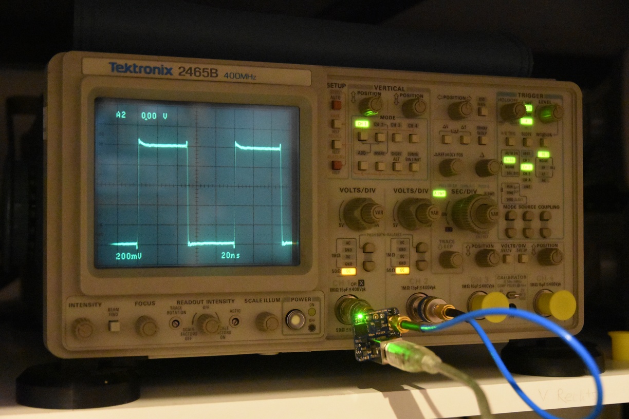
So, having all the informations I need, I made some photo(n)graphs and did a quick measurement on my Tektronix 2465B analog oscilloscope. Its specified bandwidth should be 400 MHz. By measuring the rise time \(T_\mathrm{r}\), one may estimate the analog bandwidth \(\Delta f\) by using the following equation:
\( \Delta f = \cfrac{0.35}{T_\mathrm{r}}. \)For example, if the rise time is measured in nanoseconds, the bandwidth will be stated in GHz because… physics: \( f = 1/T \).
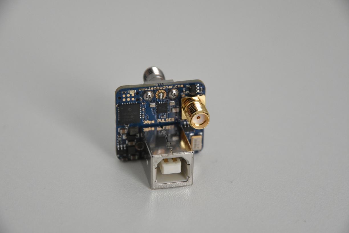
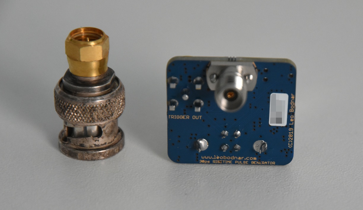
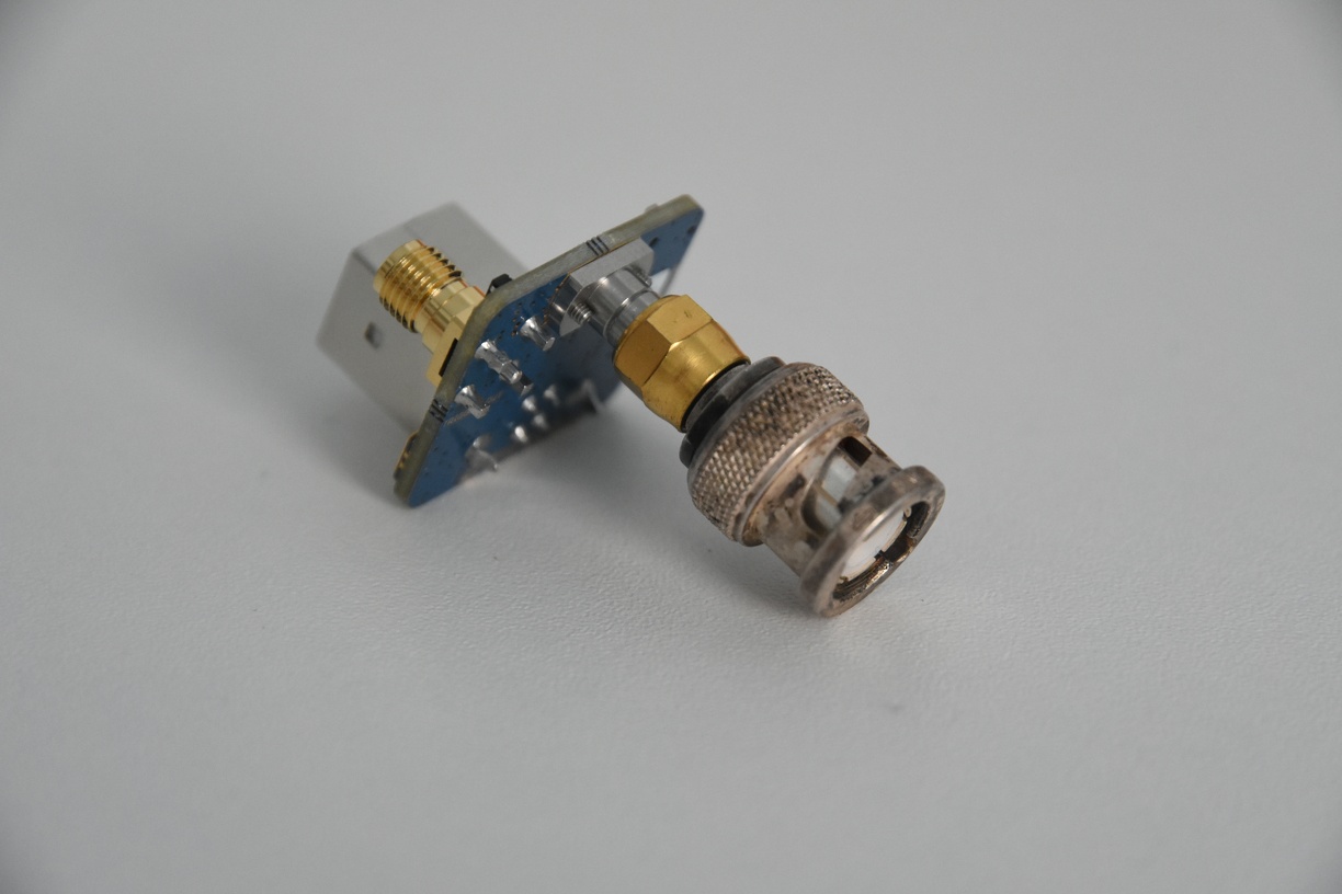
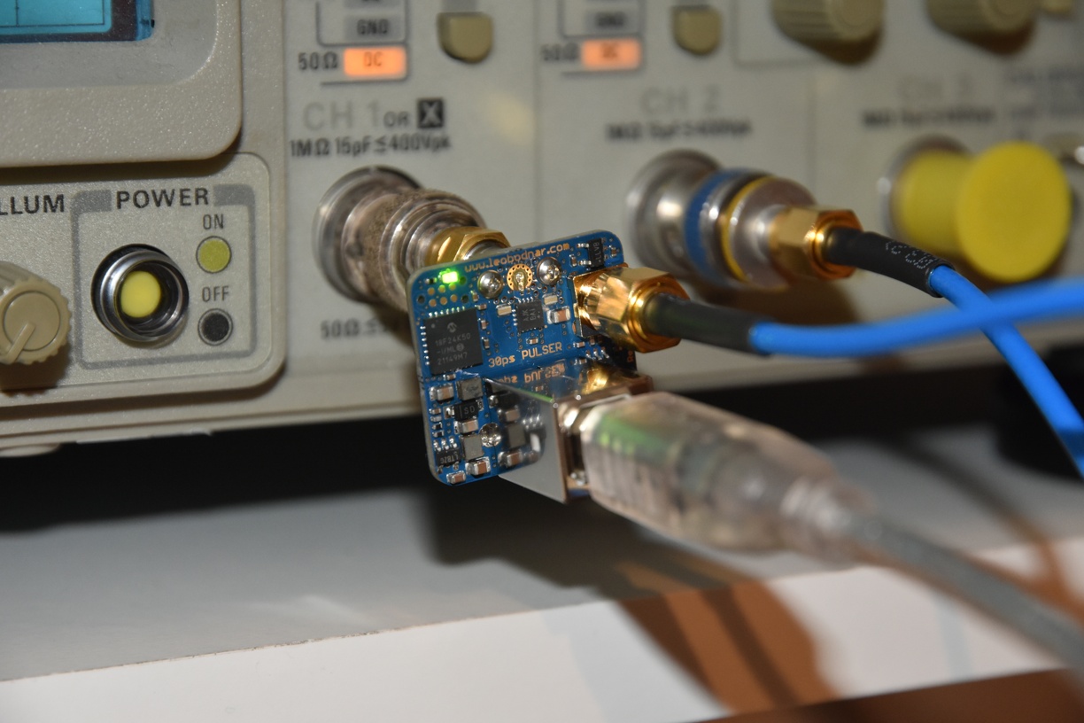
The pulse generator is a very compact device. Its dimensions are approx. 24 mm x 24 mm. It is equipped with an USB and Trigger (SMA) connectors on the front side and a oscilloscope connector (BNC, SMA or 2.92 mm microwave) on the back side. In order to operate it, one needs a USB cable with a power supply (e. g. a PC or an USB power bank), various adapters (SMA to BNC) and a short coaxial cable in order to connect the trigger output to the oscilloscope.
I ordered a SMA version of the pulse generator, however they shipped me the 2.92 mm version which is slightly more expensive (99 pounds). The shipping from UK to Germany took approx. 2 weeks and added 20% costs due to customs and shipping. Yeah, Brexit has a price tag for all of us. The 2.92 mm version has a slightly higher upper frequency specifications (40 GHz) compared to SMA (18 GHz). They provided me a calibration chart with determined rise times of approx 30 ps (rising edge) and 28 ps (falling edge).
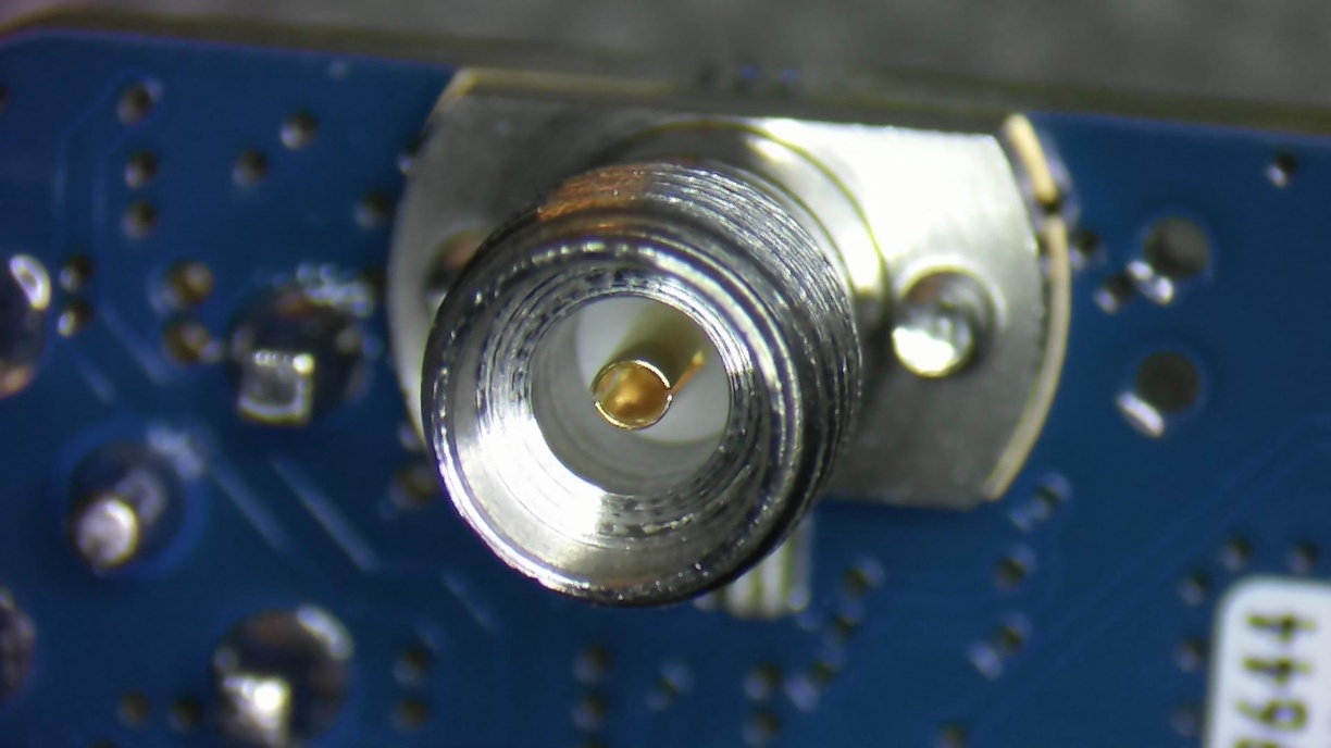
I’ve added some cool stereo microscope close-up pictures in my gallery, check them out! Here for example, one can see the center pin of the 2.92 mm connector. The center pin is surrounded by air as dielectric, as opposed to PTFE (Teflon) on a standard SMA connector. The center pin is very delicate and one has to handle it very carefully in order to minimize the wear out.
The pulser is powered via USB. The USB and SMA cables were not included. I powered the pulse generator via a battery/power bank. The RF output was connected into a 50 Ohm terminated Channel 1, the trigger output was connected to Channel 2. Trigger settings were set to Channel 2 rising edge.
The first signal one should see is a 10 MHz square wave with approx. 1 V peak to peak (1 Vpp) amplitude. If you’re using 1 MΩ termination instead of 50 Ω, the amplitude will be 2 Vpp.
Next step will be the determination of the rise time of the rising edge. One has to zoom in to the maximum value (e. g. 5 ns/div) and activate the x10 magnification. This will lead to a 500 ps/div time scale.

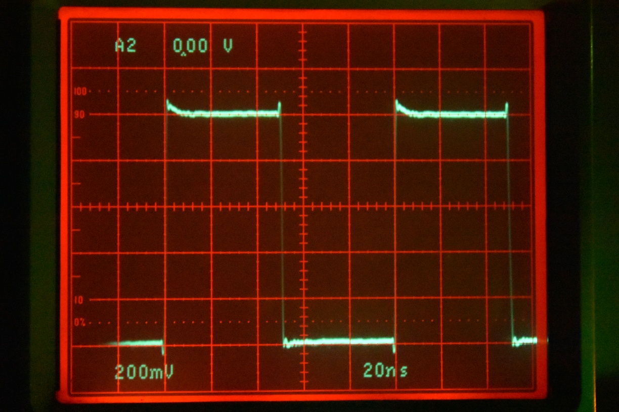
Taking the measurement is quite straight-forward. One has to determine the 10%-90% rise time. The lower image shows how the measurement is performed.
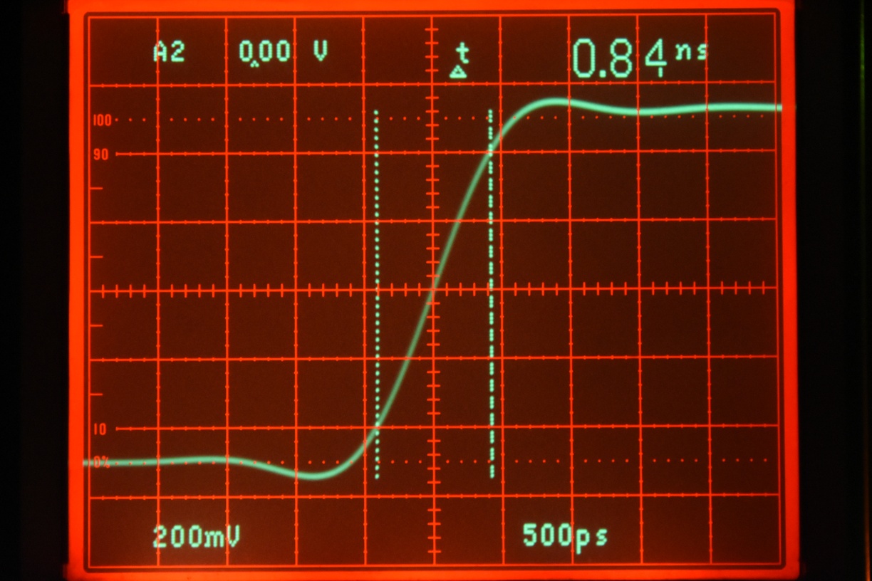
Now plugging in the measured value of \( T_\mathrm{r} = 0.84~\mathrm{ns} \) into the Bandwidth Equation gives us:
\( \Delta f~ \mathrm{[GHz]} = \cfrac{0.35}{0.84~\mathrm{ns}} = 0.416~\mathrm{GHz} = 416~\mathrm{MHz}. \)A resulting bandwidth of 416 MHz for a 400 MHz analog oscilloscope is quite acceptable! This is almost my fastest analog oscilloscope. Since I’ve acquired quite a few of Tektronix 7000 series oscilloscopes over time, I will test the pulse generator on my 500 MHz units. I’ll share the results here.
73, DH7DN
Leo Bodnar Fast Risetime Pulse Generator Read More »