Reviving an Old Temperature/Humidity Data Logger: Lufft Opus 10
Introduction
Changes of temperature may affect measurement instruments in a negative way: thermal noise, drift of operating points, thermoelectric effect etc.. Every device has a so-called temperature coefficient (short: tempco or TC) which states how the system behaves when subjected to temperature change. Tempcos have to be taken into account when designing an electrical circuit (e. g. a voltage reference or an oscillator) or running an instrument outside of defined environmental conditions. Humidity usually affects the buildup of electrostatic charge, growth of biological organisms (e. g. mold), it may accelerate corrosion of metals and may lead to changes of electrical properties of capacitors and mechanical properties of some materials such as wood or epoxy due to surface absorption of water molecules. Therefore the environmental conditions have a significant influence on any kind of measurements and therefore need to be monitored and controlled. Since the “controlling” part (a.k.a. air conditioning) can be very difficult and expensive for a hobbyist nowadays, I was interested into the “monitoring” part.
Monitoring temperature and humidity during measurements can be of great help as soon as one has to analyze and interpret long-term measurement data. Usually the crucial question is: “Can this unwanted drift of my Device Under Test be attributed to the change of environmental conditions?”. If the answer to this question is “yes”, one can decide to take appropriate measures to deal with changing environmental conditions.
Monitoring temperature and humidity can be done very easily. Everything one needs is a sheet of paper, a pen, a clock, a thermometer and a hygrometer. Writing down time, temperature and relative humidity is the simplest method of monitoring the environmental conditions. But what happens if you have to run a measurement over a span of few days or weeks? You certainly would have to deal with missing data or data gaps. This is where a temperature and relative humidity (TH) data logger comes in place as a very useful piece of test equipment. A TH data logger is basically a small computer with storage memory (e. g. SD card), a clock and temperature/humidity sensors. Modern devices have more capabilities such as WiFi connection, graphical displays, multi-sensor logging, database connection and much more. A data logger is used to monitor environmental conditions 24/7 in a laboratory or any room of a building (bathroom, basement, radio shack, storage room, …).
Computers, memory and temperature/humidity sensors have been become very affordable in recent years and can be easily turned into loggers. This can be done with inexpensive Arduino based microcontrollers or Raspberry Pi single-board computers.
Buying stuff – the devil is in the details
Me being lazy, I didn’t want to spend much time on the development of temperature loggers. I am certain that there are few interesting projects on GitHub out there which I’ll check out soon(tm). After a few weeks of searching, I found two commercial dataloggers on Kleinanzeigen (German analogy of Craigslist) in the 60-90 EUR range which is not bad at all. One of those data loggers I acquired was the Lufft Opus 10. I’ve heard of the German company Lufft before – they are a reputable company in the fields of climate and environmental measurement equipment. Opus 10 is a TH logger with a LCD display and an USB interface for readout/control of the device. It was manufactured by Lufft in the mid 2000’s and I bought a second hand unit still in a working condition – albeit the battery was already drained up and needed to be replaced soon and it will probably need a calibration.

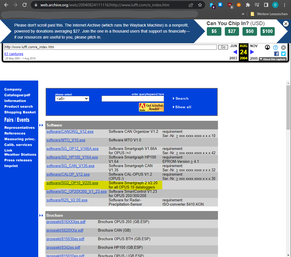
As soon as I got the TH logger, I started looking online for drivers, software and documentation. I realized that this particular product was discontinued by Lufft probably 10 years ago and there was no real support for this product. Thanks to Google search and Archive.org I was able to find the manuals, datasheets and the Lufft SmartGraph logger software.
Lufft Opus 10 teardown and battery replacement
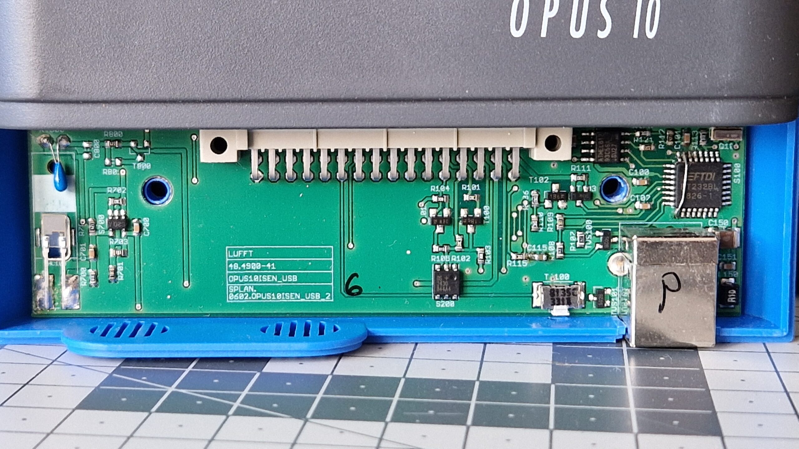
I’ve made some photographs of the inside. Opus 10 is measuring the temperature probably with a NTC resistor (blue blob) and the relative humidity with a capacitance sensor. Besides that, I couldn’t find anything unusual. FT232BL can be seen clearly, along with two EEPROM ICs. Off-the-shelf-components from the mid 2000 era were used, I haven’t seen any special circuits or ASICs.


Description of the problem
After plugging in the USB device in my PC, the device couldn’t be found and drivers had to be installed manually. Unfortunately the SmartGraph software did not contain any Opus 10 drivers so no communication could be established between the data logger and PC. I thought maybe the previous versions of SmartGraph may have the drivers included so I started downloading versions dating back to the Windows 95 era. No luck at all. No drivers could be found. Since I didn’t have the original installation CD-ROM (or diskette), I could not establish a connection to my PC. It was a bit disappointing but not bad – the device would act as a TH display for the next couple of months which was good enough for my “pen-and-paper-logging” approach.
Fast forward 4 months and the battery finally died. Luckily, the seller sent me replacement batteries which were rather special type 14500 batteries (Li-SOCl2, 3.6 V) – not the standard AA 1.5 V. Battery replacement was a piece of cake, no problem at all. But as soon as the unit woke up, it was asking for a “SET CLOCK” procedure. After checking the manual, I soon realized that I had a problem: after battery replacement, the internal data logger clock needs to be synchronized with the SmartGraph software. The following three days were an unique PTSD experience in combination with nightmares. Being a bit pissed off that I probably just bricked the unit by simply replacing the battery, I just thought “Fine, I’m going down this rabbit hole – should have done it four months ago” and try to fix this damn thing.

I don’t want to write down every step and every Trial & Error in detail. I’ll try to give the reader of this blog entry an installation procedure in a short manner so everyone using this kind of Lufft Opus Series can install the drivers and establish a connection with the PC.
Fixing the brick
During the teardown I noticed that the communication between the data logger and PC is performed via a FTDI FT232BL integrated circuit. It’s basically a USB to serial UART interface with many features, e. g. the capability to store “USB Vendor ID (VID) and Product ID (PID), Serial Number and Product Description strings in external EEPROM”. During the late 1990’s and early 2000’s, the communication of similar Opus models was usually performed via a 9-pin serial interface (also called COM-port or RS232). They must have upgraded their legacy peripherals from RS232 to USB in the early/mid 2000’s. There are probably two EEPROMs on the lower PCB: Atmel812 93C56A for sensor data and DS 2430 for USB VID/PID. I couldn’t find any microcontroller on board, since the data from the sensors need to be converted in physical units and communicated to the display. Perhaps it’s hidden under the LCD display.
Now knowing that a FT232BL integrated circuit is used inside of Opus 10 is an important bit of information because one can pin down the correct drivers provided by the manufacturer Future Technology Devices International Ltd (FTDI). Just a quick sidenote: FTDI has been confronted by plagiarism ICs in the past where their chips were copied by different Eastern Asian companies. Using a plagiarized IC with their driver can be seen as breaking the user’s license. There may be a scenario where FTDI drivers can brick a plagiarized device due to “reasons”. I haven’t observed it yet, just heard of the possibility where the drivers renders the fake IC unusable or at least it blocks its operation – so be careful and make sure you’re using the original (expensive) FTDI IC!
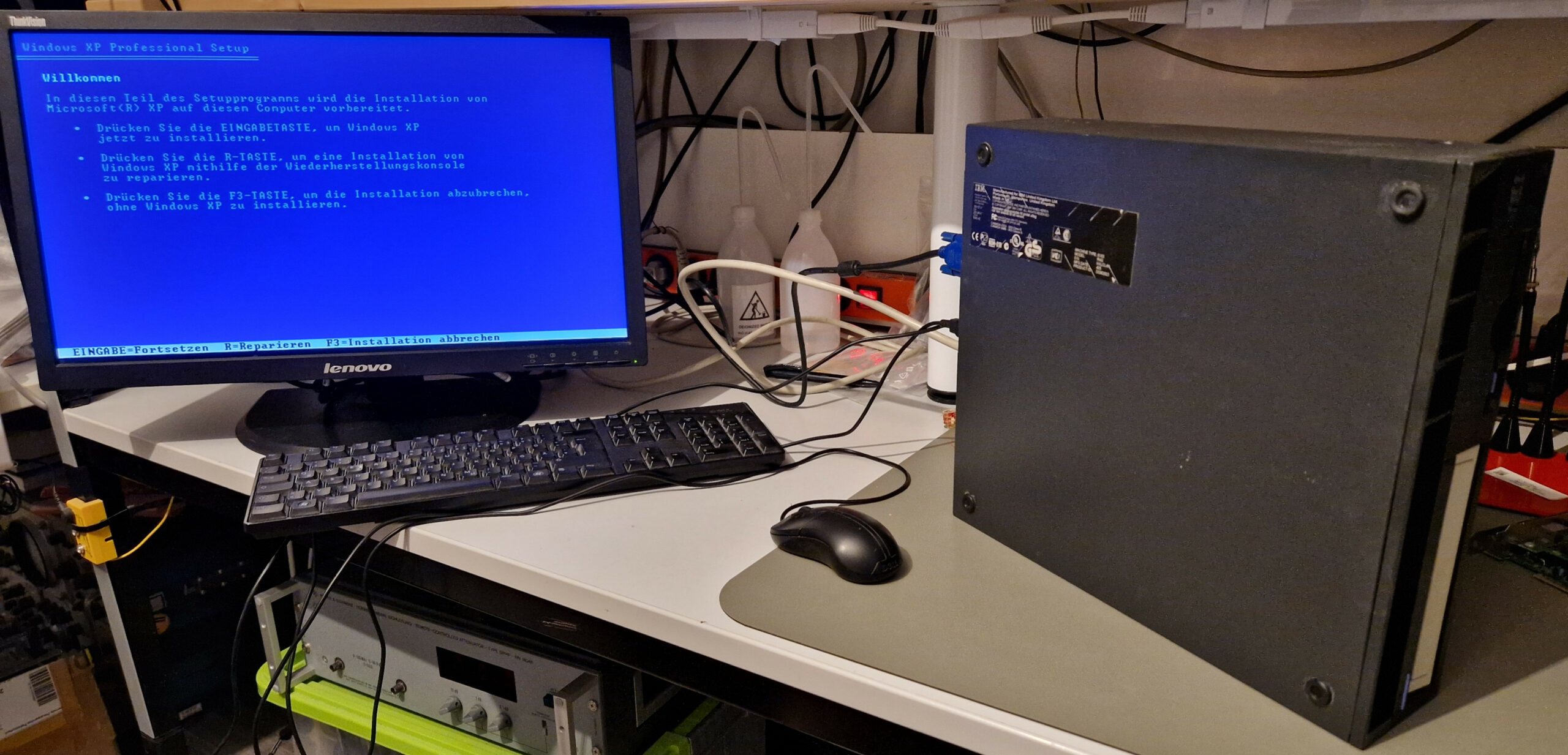
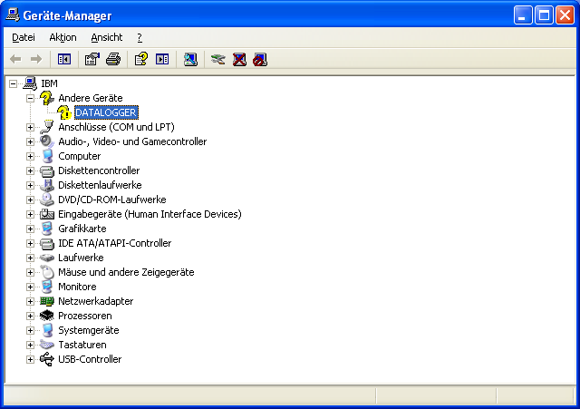
As a side project, I digged up my old IBM ThinkCentre PC from the 2004 era and installed Windows XP on it. Sometimes it’s nice to have one old PC for testing 20 year old hardware and software. After plugging in the Opus 10 into the PC, I get an unknown device called “DATALOGGER”. I wondered why the device was called that way and where did it get its name from instead of generic name such as “USB Serial Port (COM3)”. After two days of research and trying different things out, I’ve stumbled upon the FTDI Technical Note TN_100: USB Vendor ID / Product ID Guidelines. Basically FTDI ships their ICs with default VID and PID which can be customized by anyone who’s using them in their electronic designs. So basically there is a small EEPROM chip where the “DATALOGGER” name string and the custom PID are stored. Every time the USB device is plugged in, it sends those identification strings to the PC. The PC needs to find proper USB drivers which match the VID/PID. I’ve looked into the hardware description of Opus 10 and got the VID Number 0403 and PID string “D6B8\12345678”. So they customized the PID and identification strings which was a problem for the operating system. The table below helped me to identify the VID/PID associated with the FT232BL so I started looking inside of the driver INI-files for this kind of information. I’ve quickly found the 0x0403 and 0x6001 IDs and I was hoping that renaming the default PIDs into the Lufft customized ones would help the operating system with driver identification. So that’s basically what fixed the problem. I edited bunch of INI-files and after plugging in the data logger, it was recognized immediately and I was able to install the proper FTDI drivers. The FTDI Application Note AN_107: Advanced Driver Options has a bunch of additional information how to customize their driver settings.

This workaround should also work on modern PCs running Windows 7 or Windows 10.
Step-by-step procedure
(Unfortunately) I am using a German version of Windows XP. However, it should be possible to get the idea of what needs to be done. After plugging in Opus 10, check the Device Manager for the newly discovered DATALOGGER. Check its properties and look for the “Hardware Detections”. There should be somewhere the VID and PID of the device. Write down the VID/PID and download the FTDI drivers for your operating system.

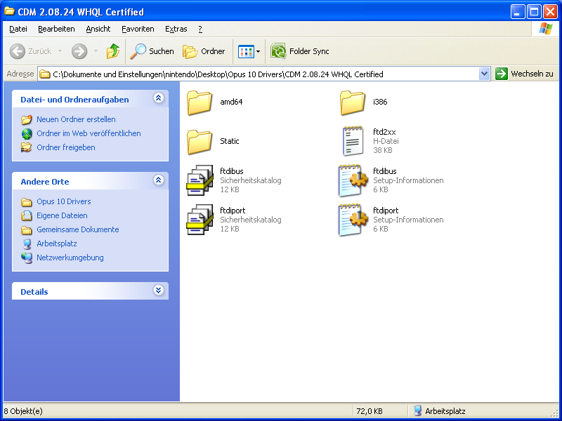
I’ve been testing many versions of the FTDI drivers but it seems there is no significant difference between them. Just get one which works on your system (WinXP x32 in my case). I’ve downloaded CDM 2.08.24 drivers from the FTDI website. Unzip the drivers and you should get a similar file and folder structure as shown here.
Next step demands the editing of ftdibus.ini and ftdiport.ini files. Just use a simple text editor. Search inside of the INI files for the PID number 6001. There should be in total 3 lines where PID_6001 appears. Replace the PID number 6001 with the newly found Opus 10 PID (e. g. D6B8).
Notice: Maybe it would be better to make a copy of the line to be edited and edit leave the PID_6001 line untouched just in case you plan to connect a FT232 based IC without custom Product ID! I haven’t tested it yet but it seems like a better approach.

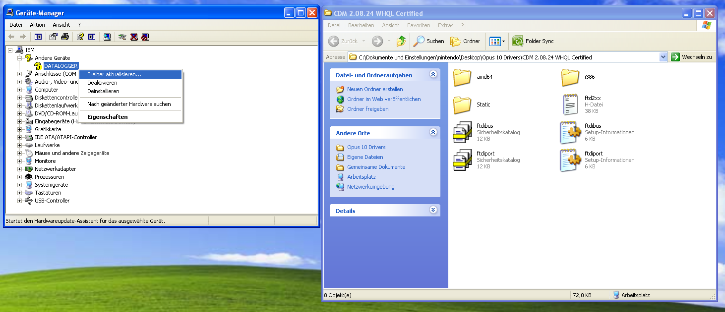
After modifying and saving the INI files, one can proceed with the DATALOGGER driver installation. Use the Device Manager and start the driver update. The driver installation wizard should be pointed to the directory with the modified INI files.
Since we’ve modified the drivers, the WHQL certification fails. This can be safely ignored. After two subsequent driver installations, the devices should appear as “USB Serial Port (COM3)” and “USB Serial Converter”.

No further changes are needed, the COM3 settings seem to be typical at 9600 baud, 8 data bits, no parity bit, 1 stop bit (a.k.a. 9600 8N1).

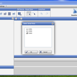
The last step demands the installation of the Lufft SmartGraph software. I’ve used version 3.0 from the year 2005. A newer, modern version v3.4.5 should work, too. The data logger should be visible as a new COMx device. With SmartGraph you can change settings of the data logger such as logging intervals, min/max alerts, physical units etc. Getting familiar with SmartGraph takes a bit of time so I leave this as an exercise to the reader 😉


Conclusion
I consider myself “lucky” because in hindsight, this fix was easy – but it was nowhere documented on the internet. The trial & error approach cost me about 2-3 days of fiddling but it was successful in the end. The other option would have been grim: the data logger would be rendered unusable unless doing further reverse engineering. This is so unacceptable! Reverse engineering wasn’t clearly my goal on a 20 year old device – otherwise I would have invested my time in DHT11/22 and Raspberry Pi programming. There was a discussion on a German Windows 10 forum dated back in the years 2018/2021 concerning Lufft Opus 10 driver installation problems but their posts didn’t provide any useful information except “tried this driver and it worked!”. One of the users apparently fixed the problem by using a Prolific driver which I have also tried out – without any success. I’ve even contacted Lufft’s Support on this matter and they kindly provided me some information and further hints what could be done.
For my part, I’ve learned again: The Internet DOES forget. Thanks to Archive.org it was possible to browse old websites and get documents and files which I needed. It’s very important to download drivers and documentation and host them on independent sites. Otherwise it will become even more difficult in the years to come to have access to information of already discontinued products.
I’m hoping that this information will be useful to other amateur radio operators because there are some similar problem descriptions concerning the usage of programmable transceivers. Those transceivers also use a USB/RS232 IC which demand certain FTDI drivers and perhaps it’s possible to revive them with a simple modification of the INI files.
73, Denis
Reviving an Old Temperature/Humidity Data Logger: Lufft Opus 10 Read More »