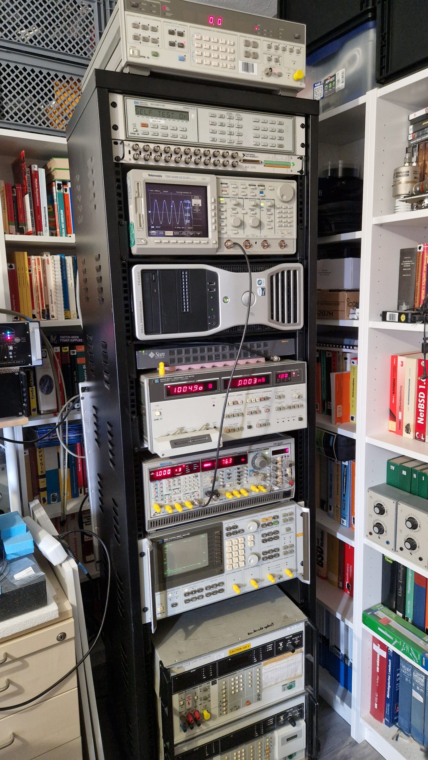
Yes, I have some kind of a Gear Acquisition Syndrome. Yes, I’m a Test Equipment Anonymous. Yes, I love Test Equipment! 🙂 However, this was bothering me for quite some time. The 19″ equipment was laying all over the place and I had some difficulties using it, since the instruments were bulky, scattered and there was no logical order as soon as I wanted to perform measurements. Luckily, a colleague of mine gave me a hint to buy a very cheap 19″ (42 HU) rack mount. This would solve few problems and also introduce new ones (more space for more equipment! Just kidding…). Anyways, I bought the rack mount and after few weeks of procrastinating, I finally equipped it with my 19″ sized test equipment. I’m pretty happy how it turned out. The most heavy parts are located at the bottom and lighter equipment is located at mid to top. It’s stable enough and won’t tip over and it can be easily moved around.
19″ Test Equipment rack mount.
Almost all instruments can be controlled remotely either via GPIB or RS232. An older Dell Workstation will be controlled via Windows Remote Desktop. Instruments from top to bottom are listed as follows:
HP 3325B – A 20 MHz frequency generator with some interesting features for audio testing
HP 3488A – Switch unit equipped with different modules. It’s used for automated, accurate and reliable signal switching or signal routing – it really depends on the used relay cards. I got few of them over the past years, e. g. types 44470A (10 CH multiplexer), 44471A (10 CH general-purpose relay module), 44472A (dual 4CH VHF switch module), 44473A (4×4 Matrix switch) and 44474A (16 bit digital I/O)
NI BNC-2090 is coupled with NI PCI-6110 (PCI multi-function-I/O-card with 4 analog inputs (12 bit, 5 MS/s per channel), 2x analog out, 8 digital I/O)
Tektronix TDS 644B, 4 CH, 500 MHz, 2 GS/s digital real-time oscilloscope. It’s a bit overkill for my audio-type applications – an excellent instrument for displaying waveforms, even RF stuff. A very useful feature is a GPIB interface for remote control and screenshot hardcopy (no need to use the disk drive)
Dell Precision T5400 workstation PC. It’s a 2007 era workstation which I bought probably around 2010 as a second hand PC. I used it like… forever. It was replaced by a faster workstation back in 2020. I haven’t dumped it because of the DVD burner and slots for 3x PCI and 3x PCIe cards. This makes it very valuable when it comes down to using data acquisition PCI cards from early to mid 2000’s era with a Win 7 or Win 10 operating system. Unfortunately this unit consumes a lot of power – it tends to heat up and it’s having thermal management difficulties during hot summers. Few of the ECC SD-RAMs failed over the past years but luckily they have been replaced easily. I tried to equip the three PCI slots with my oscilloscope cards, however, there were some serious thermal issues. I didn’t want to fry the cards so I put them inside of an external PCI expander system
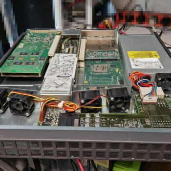
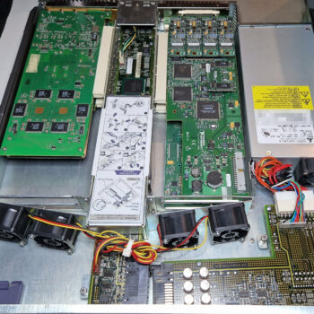
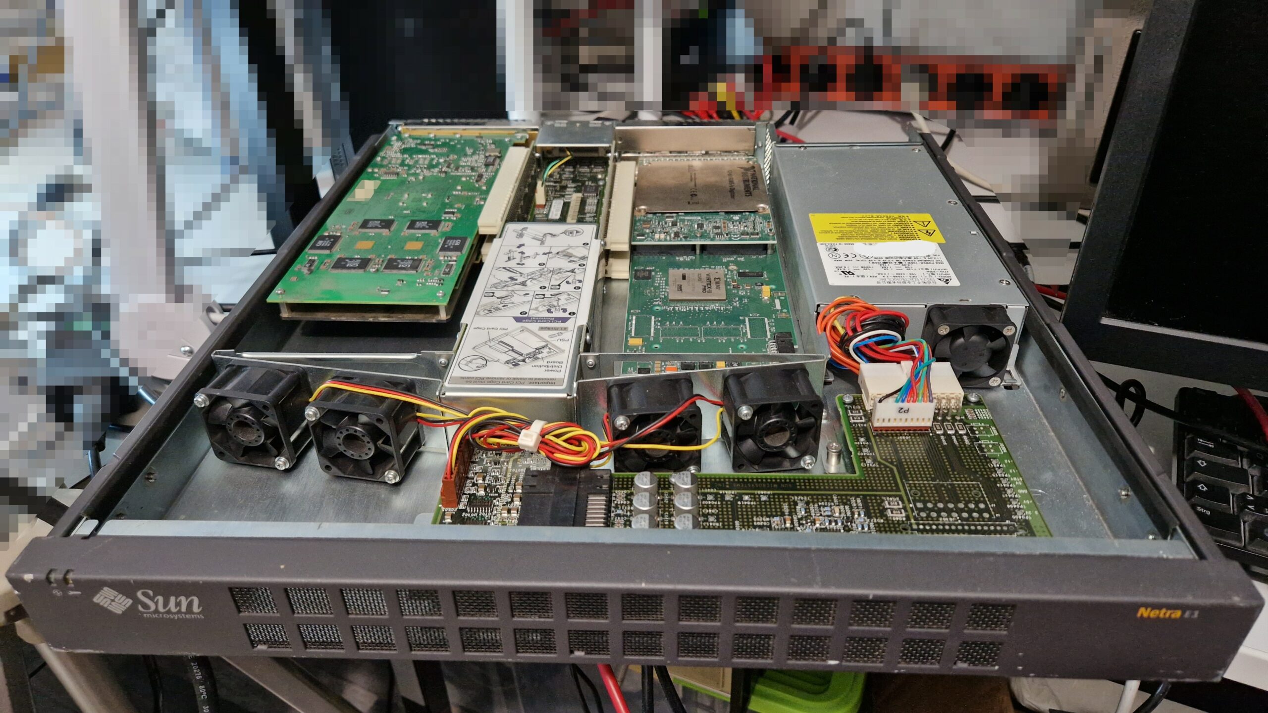
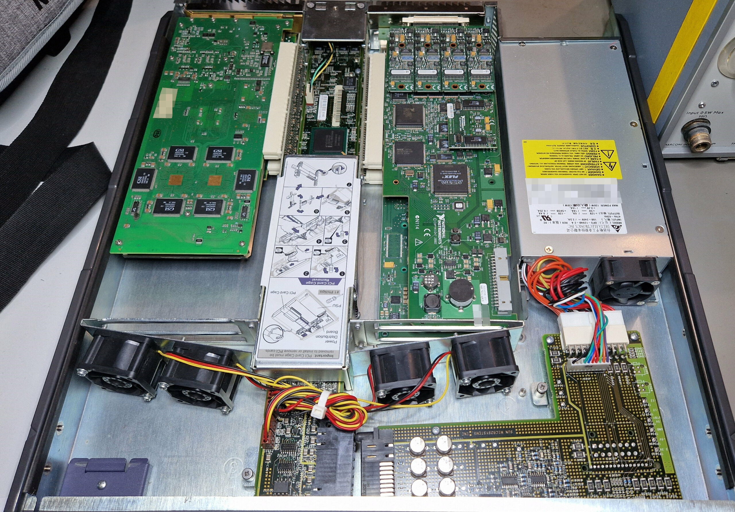
Sun Microsystems Netra E1. After having thermal issues and space problems inside of the Dell T5400, I was looking for a better solution to put the cards in a separate chassis and operate them via a PCIe/PCI bridge. Few solutions exist today, however only few are viable due to hardware/driver compatibility or power delivery constrains. The cheap expansion cards (mostly from China) can’t always deliver the 25-75 W of power to the oscilloscope card. In my case, as soon as the oscilloscope card demanded more power, the PC system crashed. After browsing eBay and looking for National Instruments’ “PXI-like” external chassis solution, I found Sun Microsystems’ Netra E1 as a viable option – however, the price was hefty. In retrospective, I’m glad I bought it because it was ready for use and it saved me a lot of time and trouble. The installation was super easy as PCI/PCIe bridge drivers exist at least since Windows XP. A downside of Netra E1 are the really loud fans. They work relentlessly at full speed; however, they keep the power-hungry cards at acceptable temperatures around 50-60 °C in comparison to 75-80 °C inside of Dell T5400!
Sun Microsystems Netra E1 – PCI Expansion System
Sun Microsystems Netra E1 – Top view.
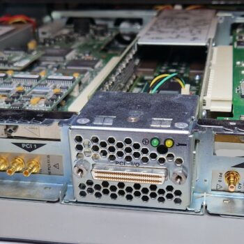
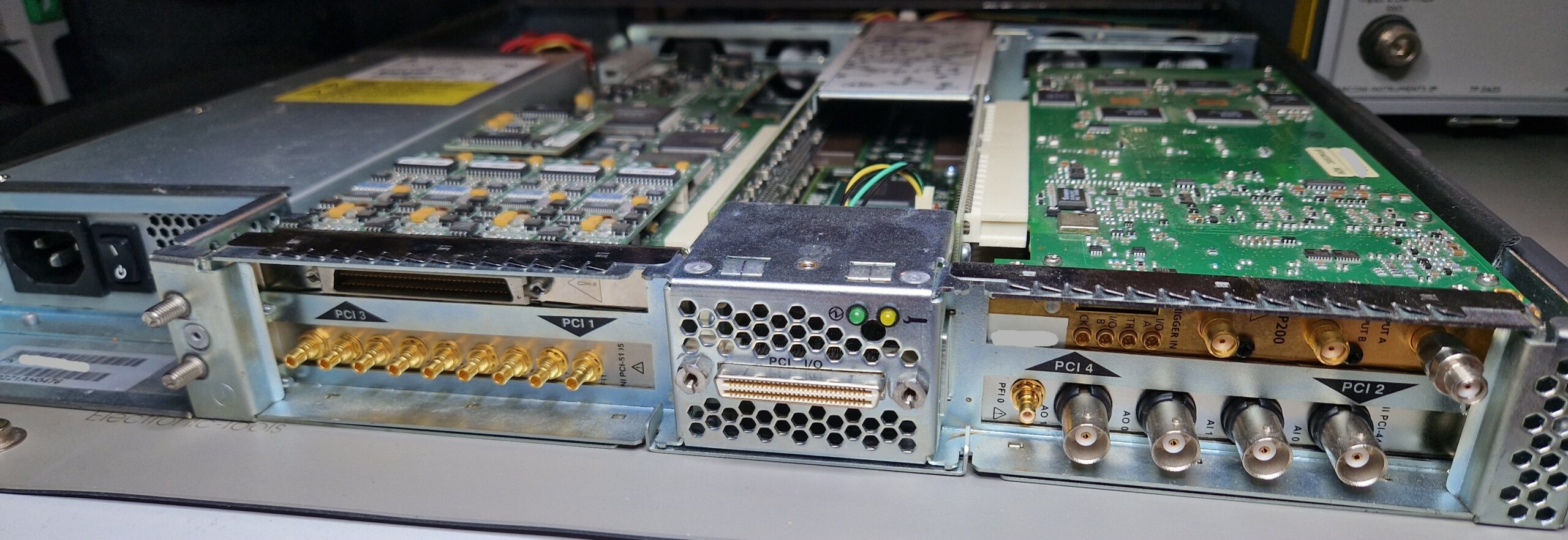
Sun Microsystems Netra E1 – Back view.
Unfortunately, Netra E1 is obsolete technology and no replacement parts exist on the 2nd hand market. Those units were produced around the year 2001 as an expansion system for Sun’s Netra Servers. I might be wrong about this but IIRC their PCI expansion product line was acquired by a company called MAGMA somewhere around mid 2000’s. MAGMA was specialized in building PCI Expander Systems for the Pro Tools Digital Audio Workstations (Pro Tools by Avid Technology, famous tor their audio/video editing software). eBay has some offers with MAGMA expansion chassis up to 16 PCI card slots, however they come at an unrealistic price of $500 to $1000, at least for a hobbyist budget. Anyways, beside the three existing PCI slots inside of the Dell workstation, I was able to put all of my four “power hungry” PCI cards (full length) inside of the 19″ chassis
NI PCI-6110: multi-function I/O card
NI PCI-5105: 8 channel, 12-bit, 60 MS/s digitizer/oscilloscope with up to 60 MHz analog bandwidth
NI PCI-4461: dynamic signal analyzer, basically a $10k sound card, still produced today – according to NI, it can be bought until 2024-12-31!
Agilent/Acqiris AP200: 1 channel, 500 MHz, 2 GS/s high-speed digitizer/averager card (used in radar tech or mass spectrometers)
Yokogawa/HP 4274A Multi-Frequency LCR Meter. I have a bunch of HP fixtures for components, unfortunately the LCR meter needs a repair. Should be hopefully an easy fix since the errors appear after warm-up. Fun fact: The Japanese government was very restrictive and protected their markets in the early days. In order to enter the Japanese market, companies from foreign countries such as United States were obliged to “team up” with a local Japanese manufacturer so they could sell their products in Japan. I guess HP teamed up with Yokogawa and Tektronix had a partnership with SONY. That’s the reason why there is occasionally a double company logo on some pieces of test equipment.
Tektronix TM5006 chassis equipped with
Tektronix FG5010, 20 MHz frequency generator (GPIB-controllable)
Tektronix AA 5001, audio analyzer capable of measuring Total Harmonic Distortion (THD), also GPIB-controllable
Tektronix SG505, audio frequency generator with exceptional ultra-low distortion sine-waves, perfect for audio amplifier testing
Tektronix DC 503, digital counter (doesn’t work, needs a repair)
HP 3562A Dynamic Signal Analyzer. A very capable FFT analyzer e. g. for audio and vibration testing and frequency response analysis in the µHz … 100 kHz regime
Fluke 5100B/5101B Calibrators. They can provide AC and DC voltages and currents and also resistances for calibration of up to 5.5 digit DMMs. Unfortunately, both need repair (power supply issues). Currently they are not in use – I’m hoping to repair them either later this year or maybe in early 2025
Surrounded by the rack mount are my book shelves with many books about physics, chemistry, operating systems and other stuff. A HPM 7177 digitizer can be seen at mid-left. There are only three cables left which are connected externally to the chassis: 230 V power, GPIB and Ethernet. I could replace GPIB with an NI GPIB-USB and Ethernet with WiFi. This would of course simplify the cable management but I’m very happy how everything turned out. I’ll need to find some lifting feet for the rack mount since it’s a bit overloaded with ~200 kg of equipment and it could cause damage the floor and the wheels over time.
Most of the test equipment seen here has been acquired during the past 3-4 years. Some pieces were really cheap (< 100 EUR), others rather expensive (> 300 EUR). It will be used for my laser interferometer and accelerometer calibration project which I plan to build in the future.
I don’t consider myself as a voltnut. I don’t design precision circuits and I don’t do crazy and expensive things like selecting, binning or matching of super-expensive components (Zener voltage references, foil resistors or opamps). I don’t spend my evenings on Christmas doing circuit simulations in LTspice. However, I like the idea of DIY-ing of an existing precision circuit design and verifying its performance. Thanks to Illya Tsemenko, Marco Reps and the voltnuts all around the world and their endless efforts in searching for the best design for a DIY voltage reference – it is nowadays possible to build a laboratory-grade, high-performance solid state voltage reference using off-the-shelf components which performs very close to their commercial available counterparts and costs just a fraction of its price (perhaps less than 10%). In this self-shaming blog entry, I want to talk about how I totally didn’t build my own voltage reference yet and how I am trying to measure ADRmu based voltage references by using CERN’s HPM7177 high-precision digitizer I also didn’t build myself. Please note: I’m not a metrologist. The reality is much more complex and the devil is always in the details. I hope that the informations provided here aren’t too far off. If so, please consider consulting ChatGPT for further guidance 😉
Voltage references – A quick summary
Voltage references are electronic devices used as a representation of the physical quantity “direct voltage” (DC volts). In the early days of DC volts metrology, voltage references were based on electro-chemical cells (Clark cell, Weston cell) before they were superseded by Josephson Voltage Standards (JVS) during the early 1970s and 1980s. Weston cells are very delicate devices and contain hazardous/toxic materials (mercury and mercury/cadmium amalgam, cadmium sulfate and mercurous paste) and therefore are not the kind of electronics device one wants to keep at home.
Quantum Metrology Porn: PTB’s Josephson Arbitrary Waveform Synthesizer (JAWS) IC (left), Programmable Josephson Junction Series (top right) and Quantum Hall Device (bottom right) as seen on Maker Faire Hannover in 2022.
JVS is the most accurate device for generation of DC voltages, however it’s very complex and expensive due to its needs for very specialized equipment (microwave feed, cryostat, probe, superconducting integrated circuit chip, readout and control system).
PTB’s Programmable Josephson Junction Series IC as seen on Maker Faire Hannover in 2018.
PTB’s Josephson Arbitrary Waveform Synthesizer (JAWS) IC as seen on Maker Faire Hannover in 2018.
There is currently only one viable and affordable voltage reference option for a precision electronics hobbyist: an ovenized Zener voltage reference. This solid state voltage reference design revolves around a subsurface (“buried”) Zener reference with a heater resistor for temperature stabilization and a temperature sensing transistor, which also compensates the temperature coefficient (TC) of the Zener reference. Ovenized Zeners are widely used as a DC volts reference in laboratories and as an integral part of high-precision test equipment such as digital multimeters (e. g. HP/Agilent/Keysight 3458A, Fluke 8588A), calibrators (Fluke 5700A, Fluke 5730A) and ADCs/DACs. They can also be used as voltage standards for digital multimeter calibration, as part of a Kelvin-Varley voltage divider or act as a so-called transfer standard – a transportable artifact with a well-known and predictable properties (stability, noise, TC) in order to “transfer” the quantity “direct voltage” between two laboratories.
Linear Technology’s LTZ1000ACH Ultra Precision Reference.
Building a world class DC voltage reference is difficult
Building a voltage reference based on Linear Technology’s LTZ1000/LTZ1000ACH or its successor Analog Devices’ ADR1000 takes a bit of effort and… money! Almost every serious design relies on precision electrical components because every component contributes to the performance of the future voltage reference. It starts with the printed circuit board (PCB). The voltnuts have figured out how to arrange the components on a PCB in order to deal with thermal gradients and thermocouple effects, electromagnetic interference (EMI), circuit protection and different sources of noise. There are many PCB designs available online, such as xDevs’ KX/FX, Dr. Frank’s LTZ1000 or Marco Reps’ ADRmu. The Gerber files can be downloaded free of charge and can be used for submission to a PCB manufacturer (e. g. JLC PCB or PCBway). You can also DIY the printed circuit board by etching the traces by yourself. Ordering a PCB would be the easy part because you get a very good quality PCB without having to deal with chemicals and drilling holes. Everything else concerning building the voltage reference can be considered as very difficult or even “hard mode”.
Voltnutting equipment. Top: two LTZ1000ACH, Mid: an early prototype of ADRmu, Bottom: Sticker, 3D-printed caps for the LTZ1000ACH (preventing air streams) and a book from Fluke “Calibration: Philosophy in Practice”, 2nd Edition. Thanks to Reps Precision Group (RPG) for design and dissemination of future ppms.
Ordering precision electronic parts isn’t a straight-forward process. In most cases, one has to check multiple online shops in order to find the suitable components. Some parts are really expensive while others are very difficult to obtain. Last time I checked the LTZ1000ACH prices at Mouser Electronics (September 2023), its was around $93 per piece (excluding VAT). The price used to be around $65 per piece before 2020. Speaking of 2020: who doesn’t remember the electronics components shortage which resulted in LTZ1000 lead times up to 52 weeks (Mouser, DigiKey, Farnell, …)? This was a real thing just about half a year ago. Meanwhile, the stocks have been replenished. However, the prices have risen significantly (+30%) compared to pre COVID-19 times. Buying precision electronic parts off second hand market (eBay, craigslist) can be a winner but I would consider this as a gamble . Depending on your source, there is always a risk of buying counterfeit, defective parts or parts with a poor performance. Precision resistors, which are needed according to the Linear Technology’s reference design, are also very expensive ($25..30 per piece, 4 needed) and difficult to obtain. Another difficult to obtain components are the low thermal EMF binding posts (~ $25 per set). I participated in an EEVblog group buy which took about 2 months from placing the order until receiving the binding posts (Thanks to branadic! This was entirely done voluntary by him and free of extra charges). Just be aware of those time and money sinks.
Low thermal EMF binding posts. Thanks to branadic at EEVblog for taking care of the group order from Asia.
Building an ovenized Zener voltage reference ought to be a long-term project of mine. I don’t want to rush things and plan to accumulate the necessary components over time, perhaps during a timeframe of 2 to 3 years. I already have two LTZ1000ACH waiting in my desk but everything else is missing. I need to order the precision resistors, the PCBs, the enclosures, transformer cores and I have to find some time for assembly.
Precision parts have arrived – what’s next?
Once you have obtained the essential parts, you’re ready to do the assembly. But hold on for a second – you have to know what you’re doing and you have to do it very carefully. For example, if you apply too much heat when soldering your precision resistors or LTZ1000 to the PCB, it can result in a disaster. Overheating a precision resistor can either damage it and render the specifications void or introduce an unwanted hysteresis, which makes it either susceptible to temperature changes or drift over time. Those drifts directly influence the stability of the future voltage reference and greatly reduce its performance. Assembly is crucial and early-made errors are punished much later in the future. And don’t forget the obligatory bottle cap in order to prevent air streams. Be careful when handling precision electronics parts: always wear gloves to prevent contamination with grease/dirt and also take ESD precautions. Try to use quality parts over “Chinesium”.
ADRmu
In order to kick-start the project, I was fortunate to grab one ADR1000-based ADRmu for myself, which Marco built and tempco-tuned by himself. I needed a point where I would be able to get started with DCV metrology and to accumulate few thousand hours of operation time. One of the ADRmu’s design goals was to be compatible with LTZ1000(ACH) and ADR1000. ADRmu has protection circuits, a gain stage to shift the voltage from typically 7.2 V to a value close to 10 V and an eXtReMe isolation transformer for common-mode suppression. It’s possible to fine-tune the gain stage with discrete resistors in order to get the voltage output close to 10 V (if necessary). Very interesting features of Marco’s design is the possibility of use of resistor networks with an option for using discrete precision resistors. Resistor networks consist of thin film resistors manufactured in one process, which are thermally coupled through their substrate and hermetically sealed inside of their package. A resistor network has a very stable resistance ratio (e. g. 13 kΩ/1 Ωk) which is crucial for the LTZ1000(ACH) stability. That’s an advantage compared to discrete resistors (e. g. 13 kΩ and 1 kΩ) which have their own TC and drifting characteristics and therefore contribute to the performance of the LTZ1000(ACH) circuit.
Innards of ADRmu, Marco’s voltage reference design.
Once it’s built – the adventure starts
Once you have built your voltage reference, it’s time for the first measurement. Depending on the voltage reference, this measurement should be done with a high accuracy DMM under stable environmental conditions with proper leads. Typically it can be done with a 6.5 digit DMM (HP 34401A, Keithley 2000) or even better ones, such as 7.5 digit (Keysight 34470A, Keithley 2001) or maybe 8.5 digit class DMM (e. g. Keysight 3458A, Keithley 2002, Datron 1281 etc.). During the first several months or maybe during the first year of operation, the voltage reference will show some kind of measurable drift. The magnitude of this drift will be in the range of few ppm (2…5 ppm/year maybe, just to name some numbers).
Voltnutting equipment shown at Maker Faire Hannover 2022: Keithley 2400 SourceMeter (top), HP 3458A (middle), Fluke 5700A (bottom). HP 3458A is running in 7.5 digit mode (d’oh!).
This is a well-known property of solid state voltage references. Initially they drift few ppm over time but settle after many hundreds or thousands of hours of operation. It’s called “aging” and the reasons for aging processes are hidden behind the “semiconductor physics curtains” (changes in mechanical stresses acting on the semiconductor, outgassing and diffusion processes, electrical changes in the circuit elements). Also power-cycling a voltage reference can lead to so-called hysteresis due to thermal shocks which are experienced during powering on/off the oven (having a ΔT of 40-60 °C in a precision semiconductor circuit isn’t very healthy). So the goal is to keep the voltage reference powered on permanently, at least for months or perhaps years. Voltnuts are serious about this issue and rely on uninterruptible power sources (UPS). Good and stable voltage references change in the order of <0.3 ppm per month – not every voltage reference will reach this kind of performance “out of the box”. It is possible to select best-performing Zeners from a production sample. However, it’s an expensive gamble if you plan to select maybe two or three “good ones” out of 20.
In order to get reliable and somewhat predictable results, every voltage reference needs to be characterized in terms of stability, low-frequency noise and temperature coefficient. A voltage reference with an unpredictable drift is basically worthless because it doesn’t meet the stability criteria and therefore doesn’t qualify as a reference or standard. Currently I’m not able to do the noise and TC characterization yet because of lack of a ultra low-noise amplifier and a climate chamber. That’s another rabbit hole which has to be skipped yet 😉
How do you measure the stability of a world class DC voltage reference?
A high-accuracy DMM such as Keysight 3458A has built in a LTZ1000(ACH) as a voltage reference for its ADC. What happens if we measure another LTZ1000 with this kind of meter? We are basically comparing two similar voltage references to each other. Now let’s suppose the DMM’s internal DC volts reference shifts for 1 ppm. As a consequence, the indicator on the DMM’s display would show a voltage shift of 1 ppm. But in reality, we wouldn’t know if our instrument’s internal DC volts reference or our Device Under Test (DUT) shifted! The only way to know which one changed (DUT or DMM) is by comparison between a larger number of voltage references (e. g. 2, 3 or 4). One possibility would be to use two Keysight 3458A to measure one voltage reference. This way it would be possible to identify whether one of the DMMs or the DUT shifted. Since a 8.5 digit DMM is a very expensive piece of equipment, it’s much cheaper to build few more DC volts references and compare them to each other within a group of references.
So the answer to the question would be: one rather compares the voltage differences between multiple voltage references and observes the long-term stability between them. This is usually done with a calibrated high-accuracy DMM or (if you’re a vintage kind of a guy) so-called Null Detector. This way we are gaining confidence in the stability of the DC voltage reference and simultaneously we’re building a calibration history of each unit.
CERN’s HPM7177
I do own a HP 34401A (6.5 digit DMM) which is good enough for 99% of measurements but not good enough for voltnutting or DC volts metrology stuff. 6.5 digit metrology isn’t something I really look forward to do (like some guys over at EEVblog). In order to monitor the stability of my voltage reference(s), I’ll need a 8.5 digit class meter. Since the market for HP 3458A is currently overheated and buying such an expensive device is associated with potential risks (bad or drifty U180 ADC), there might be a possible alternative within a hobbyist’s budget.
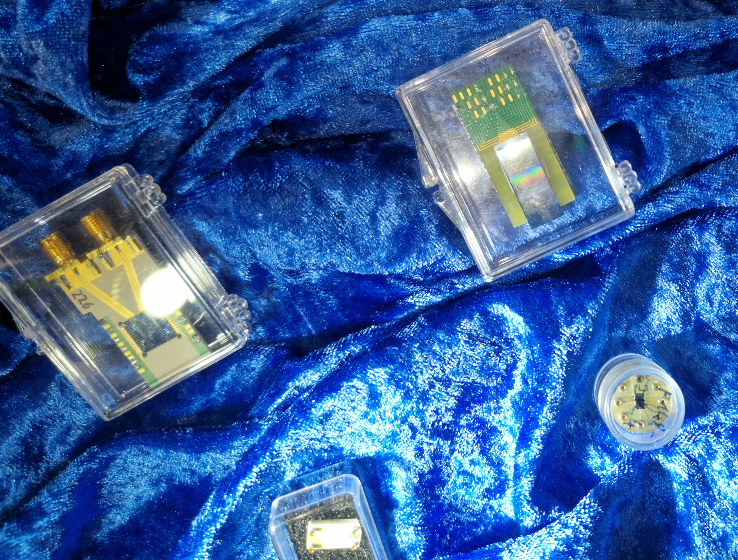
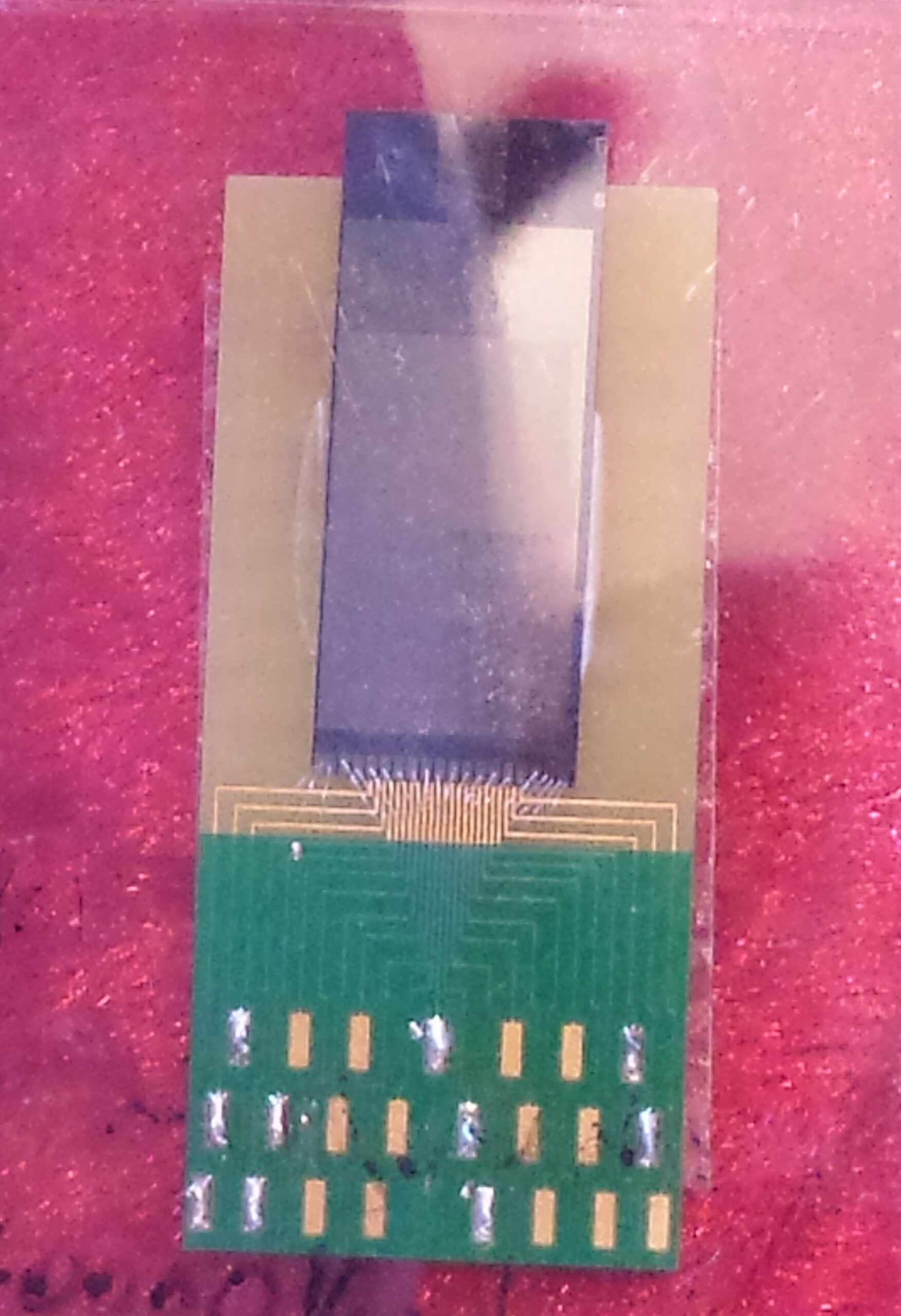
HPM7177 sitting there and gaining ppm dust. It’s a beautiful design and very well crafted by A Random German Guy (ifyouknowwhatimean).
Few years ago, CERN TE-EPC group’s member Nikolai Beev has proposed a design of a metrology-grade ADC called HPM7177 which has been published as an Open Hardware project in the meanwhile. HPM7177 is based on Analog Devices’ AD7177-2 Sigma-Delta ADC, Linear Technology’s (now Analog Devices) LTZ1000ACH ultra precision reference and Vishay’s PRND Thin Film Resistors. It’s a single channel ADC card with a native sampling frequency of 10k SPS with a maximum bandwidth of 5 kHz. An effective resolution of 23 bit for a bandwidth below 10 Hz can be obtained. The measuring range is ±10 V with a 30% over-range. A really nice feature are the thermo-electric coolers for temperature stabilization of the temperature sensitive parts.
Two HPM7177 units have been built by Marco. He documented the assembly in one of his YouTube videos. I “inherited” this HPM7177 from That Random German Guy 😉 some time ago. However, I wasn’t able to use it due to lack of time, projects and most importantly: I wasn’t able to do a proper calibration of this metrology-grade ADC. Meanwhile it’s been powered up since March 2023 and a calibration and characterization has been performed in May 2023.
One small downside of HPM7177 is its inconvenient operation: the incoming data is encoded as a 32-bit integer, which it needs to be read out via USB at a fixed sample rate of 10 kHz and post-processed after data acquisition. Recording all samples generates a huge amount of data in the order of 100-250 kB/s. This is no problem for a modern-day computer and Python, however, long-term measurements may generate lots of gigabytes of data very easily. At a certain point it’s becoming highly impractical to save raw data in a human-readable CSV file so one has to consider using different formats such as NASA’s HDF5.
Soon™
HPM7177 has been powered since early 2023. Let’s hope the internal references did not drift too much. Next calibration in 1-2 years will tell.
Alright, this is already too much text I’ve written as an introduction to my voltnutting ambitions. I’ll write another (shorter) blog post how I did the calibration of HPM7177 and share some measurement results. There will also be some integral nonlinearity (INL) measurement results here which I was able to perform with suitable instruments.