Introduction
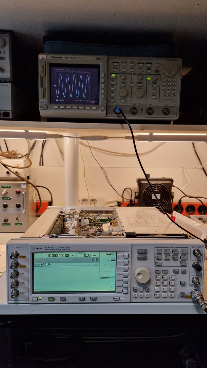
About a year ago, I bought an Agilent E4432B ESG-D Series Signal Generator on eBay. Those signal generators are used in the area of analog and digital wireless communications system testing. The frequency range of my model goes from 250 kHz up to 3.0 GHz, the maximum radio frequency (RF) power output into a 50 Ω termination is in the range from +17 dBm to -136 dBm. This instrument will be useful in a different project of mine where I need a good spectral quality sinewave at frequencies of about 80 MHz for mixing RF signals. Another very useful feature is the ability to modulate the carrier frequency (AM or FM) which can be demodulated by a Software Defined Radio (SDR). It can be automated via GPIB and synchronized to a 10 MHz reference. Due to its high broad frequency coverage and level accuracy, it would be useful to test my (currently broken) spectrum analyzers, too. Unfortunately, my eBay score had a flaw which I want to talk about.

Problems with the Step Attenuator
The unit I received is about 15-20 years old and had already approx. 61000 operating hours (equals to ~7 years of 24/7 operation) and 770 power cycles. It was overall in a good shape although one of the external input BNC jacks was loose and had a slightly damaged thread. After turning the signal generator on, I ran the diagnosis and no faults or errors occurred. I tried to set up an RF signal output at different frequencies and I noticed a very uncommon behavior: there was a sinewave at set frequencies in the range from 250 kHz up to 400 MHz (max. analog bandwidth of my oscilloscope) but the signal wasn’t present at certain amplitude levels. I checked the different amplitude levels noticed some kind of a strange pattern (see Table 1).
| Amplitude (dBm) | -60 | -55 | -50 | -45 | -40 | -35 | -30 | -25 | -20 | -15 | -10 | -5 | 0 |
| Signal present? | ? | + | + | – | – | + | + | – | – | + | + | – | – |
The signal at -60 dBm and lower amplitudes was too weak for my oscilloscope to detect but the pattern indicated a problem. Luckily I’ve seen a repair video by Shahriar of TheSignalPath some time before acquiring this signal generator where he had a similar unit on the healing bench with identical symptoms. This kind of problem seems to occur in HP/Agilent test equipment (e. g. Types HP 8648A or E4400 Series signal generators or HP spectrum analyzers) where mechanical attenuators are actuated by solenoids. The detailed construction and working principle of the mechanical step attenuator is well explained in Shahriar’s video. There is also a very good repair video from YouTube user idpromnut where I got many useful repair tips.

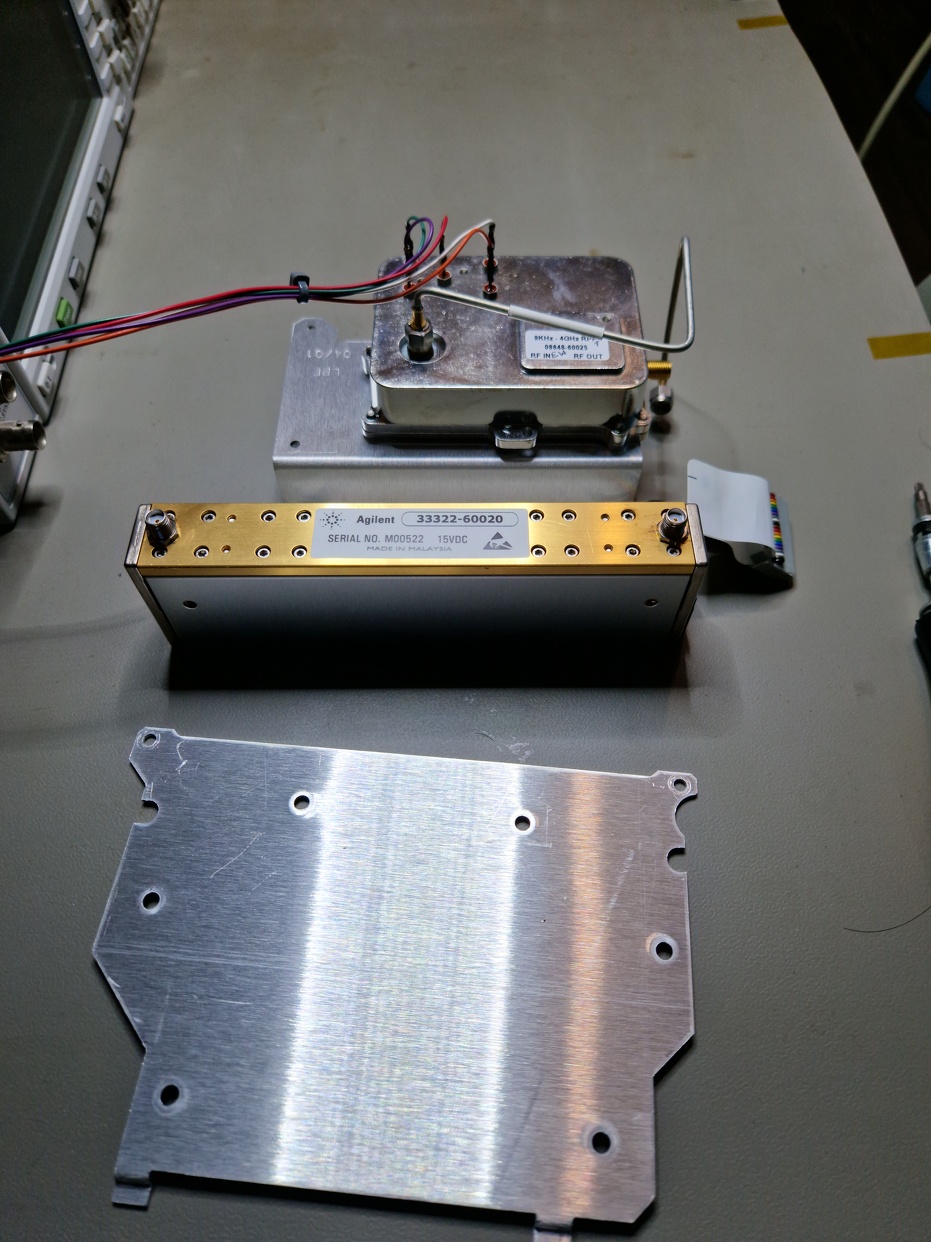
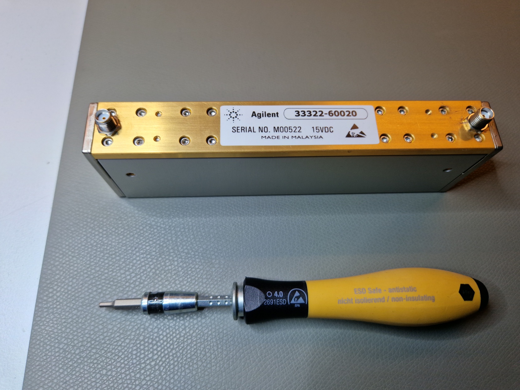
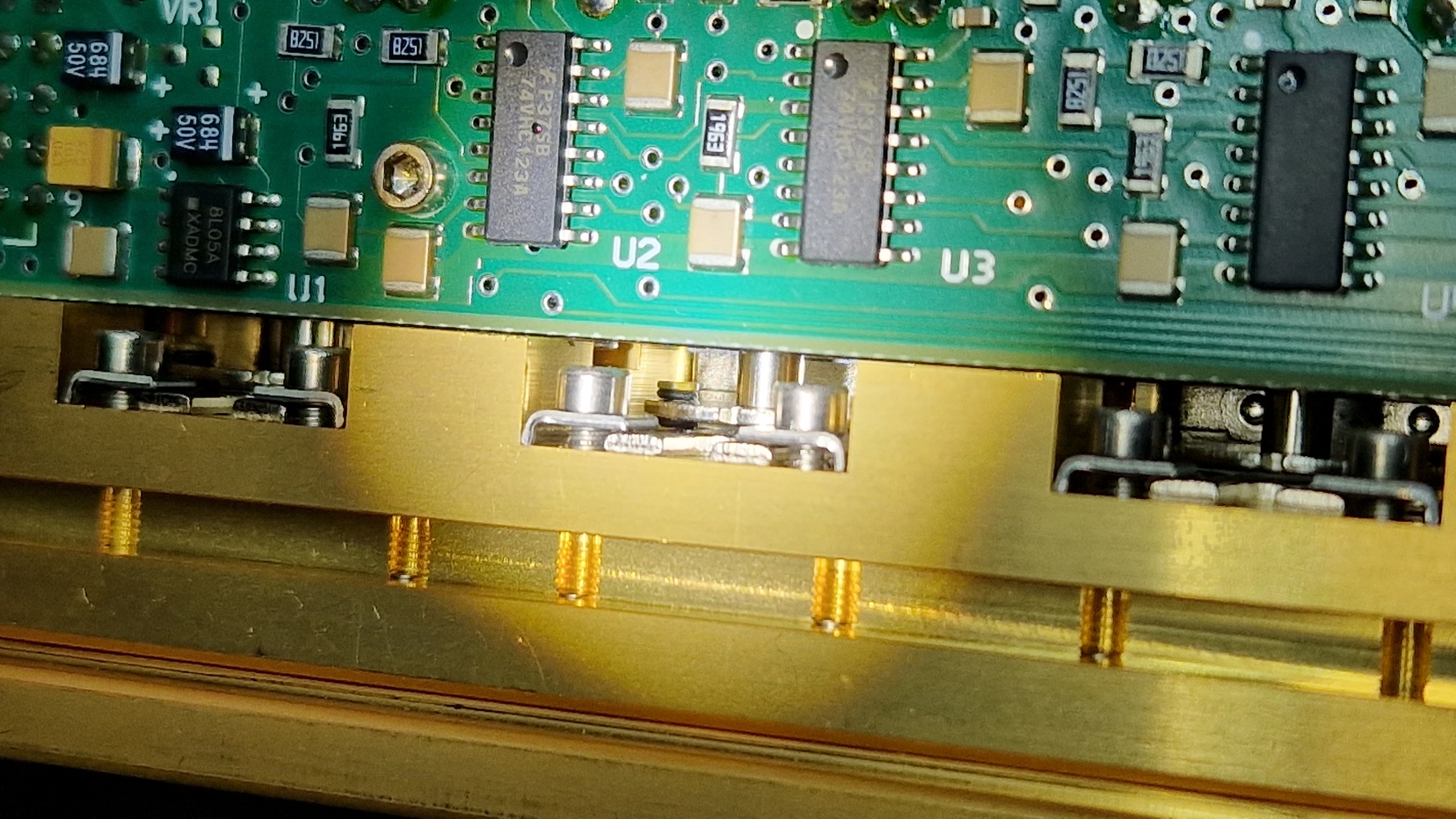
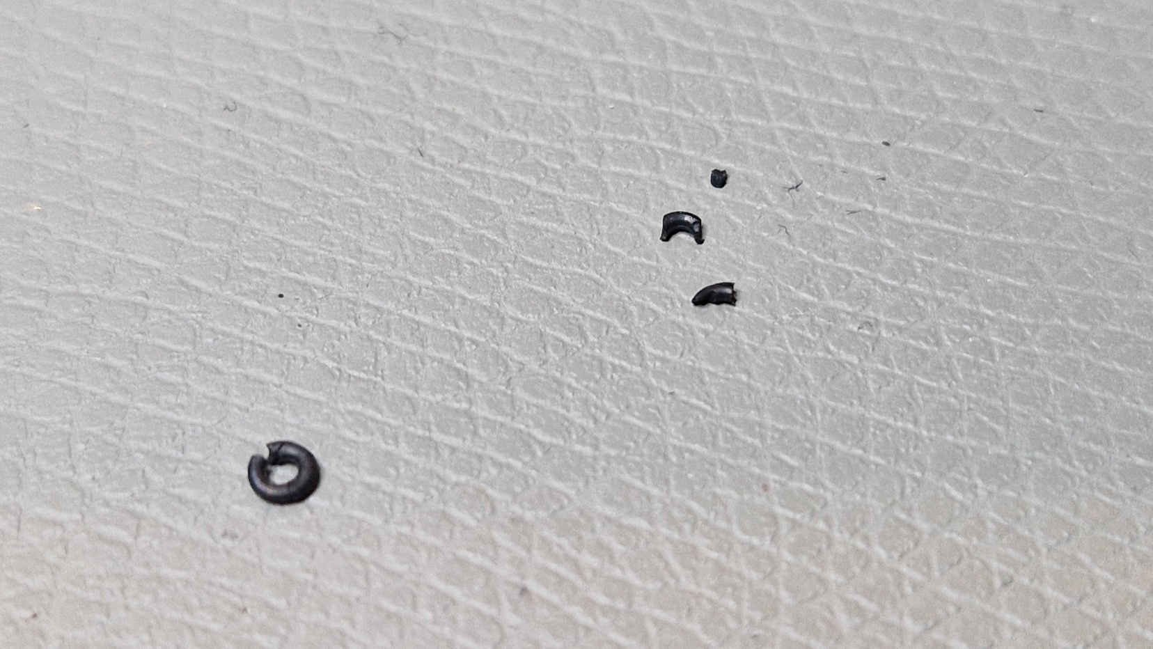
While changing the attenuation range in steps of 5/10/20/40/60 dBm, the corresponding solenoid exerts a force on very small rubber O-rings which are used as an interface between a metal plate and plastic plungers (see photos). The plastic plungers are connected to metal strips which are pushed onto resistor traces in order to make electrical contact with a corresponding attenuation resistor. Over time, the O-rings lose their flexibility, become brittle and are either crushed by the actuating mechanics or just fall off their spot. This impairs the ability to switch the attenuator levels properly. Checking the instrument diagnosis revealed over 660k attenuator cycles which supports the faulty O-ring assumption. Luckily, this fault is easily repairable to a certain degree without having to disassemble the delicate RF parts. Buying a new attenuator wasn’t an option because the current prices on eBay are in the order of $500 per attenuator. The signal generator is worth $700 – $1200 depending on measurement capabilities/installed options so replacing the attenuator would hurt the hobby budget.

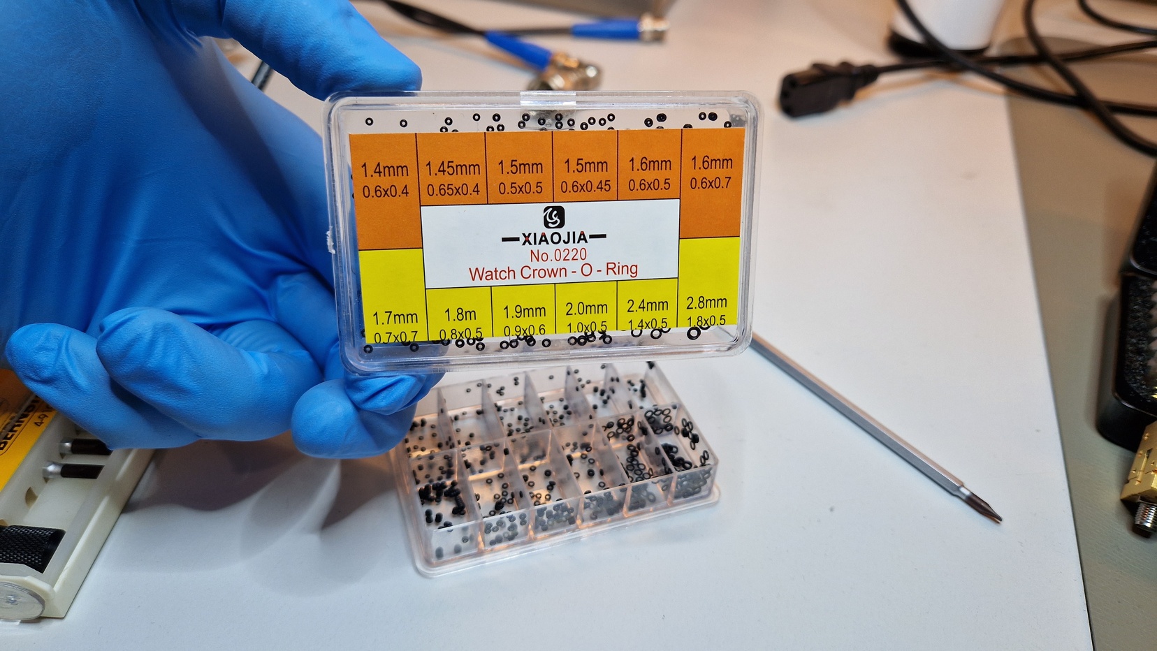
In order to repair the attenuator, the O-rings have either to be replaced or glued with a flexible epoxy according to TheSignalPath video. I’ve chosen the replacement method since I don’t have proper epoxy glue. However, idpromnut showed in his attenuator repair video the replacement procedure of O-rings on a similar unit. He suggested to buy “Wrist watch clock Crown-O-Rings” on eBay from RUIHUA No. CO-12. It’s a set of O-rings in different sizes used by watchmakers. I ordered mine from XIAOJIA for approx 9 EUR. The replacement O-ring size is “2.0mm 1.0×0.5” (2.0 mm outer diameter, 1.0 mm inner diameter and thickness 0.5 mm).
Repair Attempt
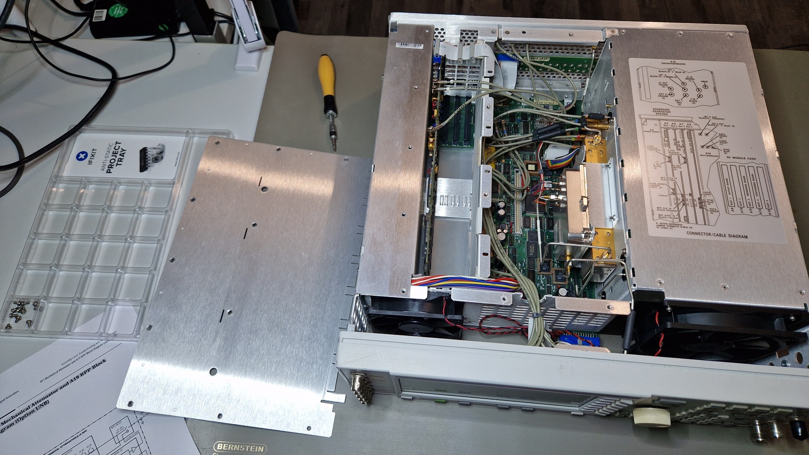
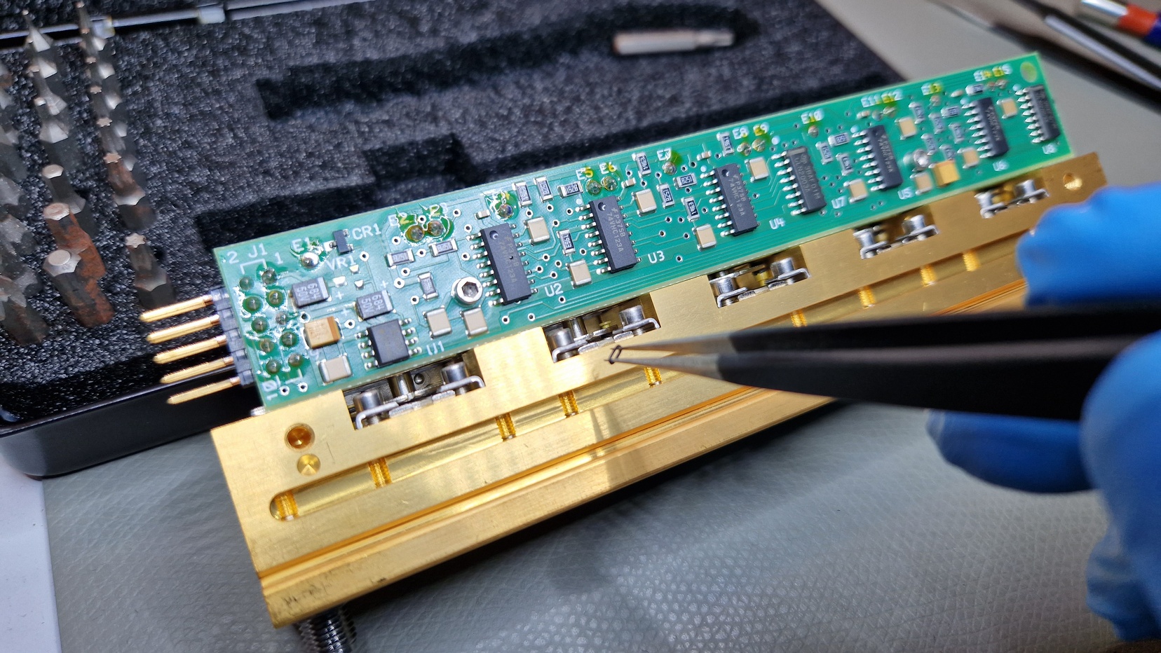
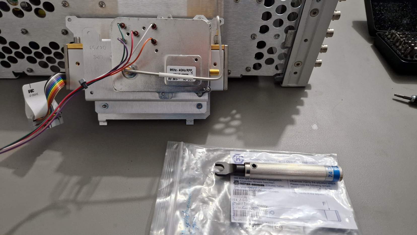
Fast forward to August 2022. Back in June 2021 I didn’t have the right lab equipment and spare time. It wasn’t a high priority repair so more than a year passed by. Meanwhile I acquired enough lab equipment to start a repair attempt. My basic tools were: screwdriver with hex/torx bits, flashlight, magnification glass, tweezers and a 1 Nm torque wrench for the SMD connectors. I was a bit paranoid concerning electrostatic-sensitive devices (ESD) so I used an ESD mat and ESD-compliant tools during repair. Wearing latex gloves proved to be useful because of ESD matters and avoiding contamination of sensitive parts and metal surfaces with grease or fingerprints. I had access to other tools like torque screwdriver and a stereo microscope for additional delicate work which weren’t necessary for this repair. I cleaned my lab prior to this repair attempt in order to remove as much dust as possible to mitigate the contamination of the (ESD-)sensitive electronics. I’ll post some pictures showing the repair steps. I’ve uploaded many more pictures into my Piwigo Photo Gallery. Check them out if you want to see more high-resolution images.
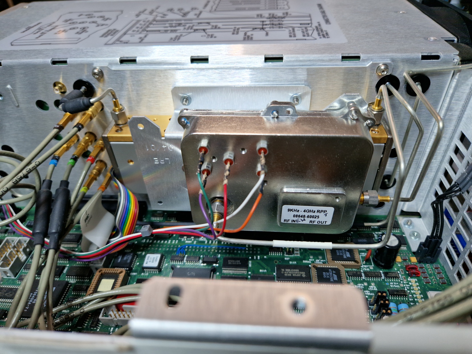
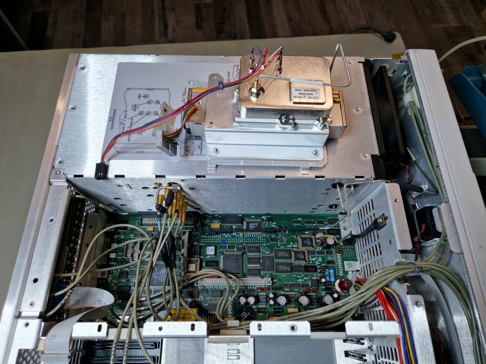
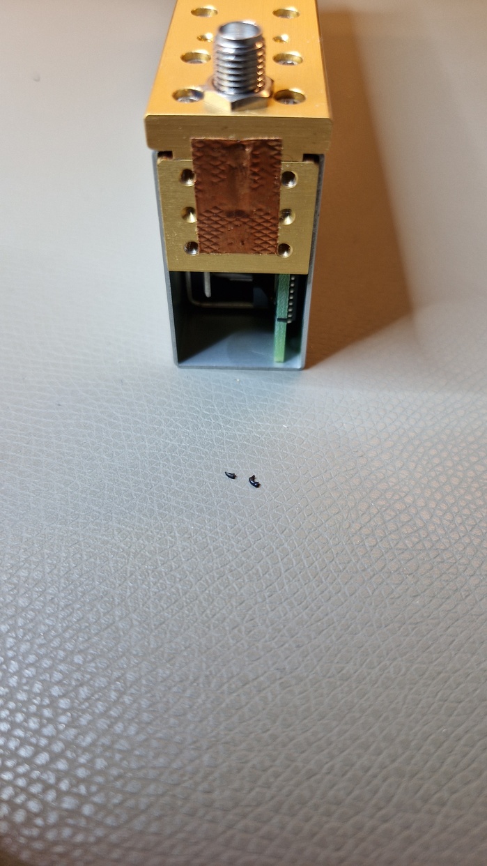
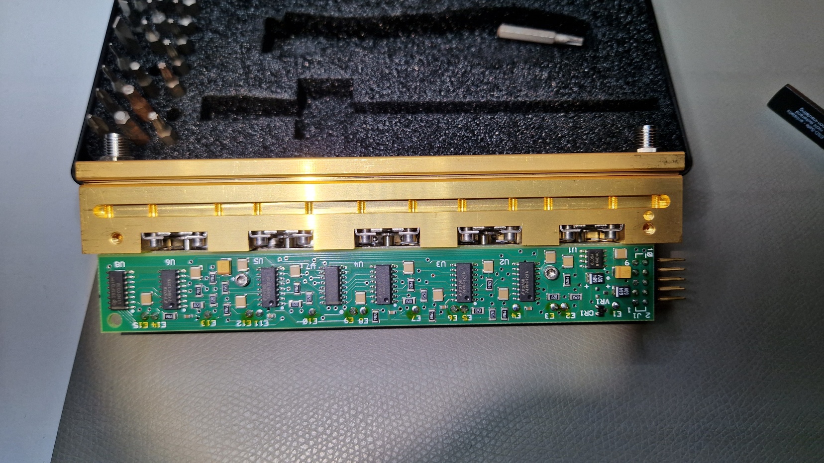
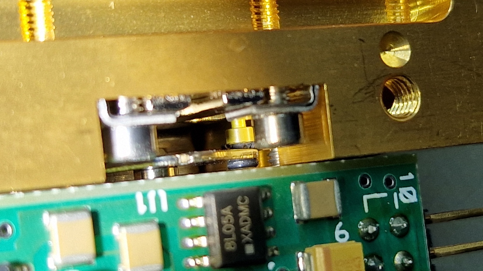
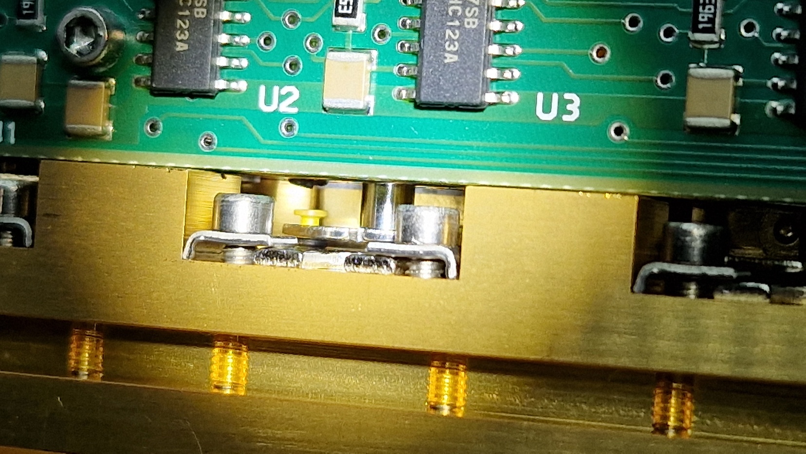
At this point, the visual inspection showed one attenuator where O-rings were missing. Other stages were in a decent working condition. However, the impending failure was clearly visible. I decided not to disassemble the whole unit and try to insert new O-rings. This had to be done by fiddling around with tweezers and trial-and-error. It took me about two hours to insert two O-rings. In the end, they fitted perfectly.
Summary and Conclusion
I would consider this repair as “easy” thanks to TheSignalPath and idpromnut‘s detailled repair videos. I couldn’t do it by myself because I’m not an RF test equipment expert and I haven’t done such repairs before. It’s just another hobby and I’m relying on some help from the outside. However, this repair was very rewarding and only temporary. The visual inspection showed the impending failure of the remaining O-rings. Servicing this unit will surely be necessary somewhere in the future. I’ll have to replace every O-ring to be sure they won’t fail again for the next few years.
Also one has to consider post-repair procedures as the service manual suggests. I haven’t checked the amplitude over the frequency range because of limited measurement capabilities. I just recently acquired a RF power meter which has to be calibrated first. My spectrum analyzers only cover the frequency range up to 1…1.8 GHz and aren’t very trustworthy. I’ll also have to check the post-repair performance of the step attenuator with a Vector Network Analyzer (e. g. NanoVNA V2 Plus4) in order to be sure the unit is working properly.