
Introduction
About a year ago I saw one of CuriousMarc’s YouTube videos on repairing a Xerox Alto computer. CuriousMarc published shortly afterwards an episode, which compared the Tauntek LogICTester with the TL866II+ EEPROM programmer which has some transistor-transistor logic (TTL) testing capabilities. 1970’s and 1980’s era test equipment used alot of those intergrated circuits (IC) in order to operate. Servicing or repair of older test equipment like oscilloscopes, multifunction calibrators, power supplies etc. will be much easier with tools such as a logic tester. After reading a very positive review from a friend at the Wellenkino, I thought it would be very nice to own such a tester for servicing or repairing my (broken) equipment.
Tauntek LogIC Tester
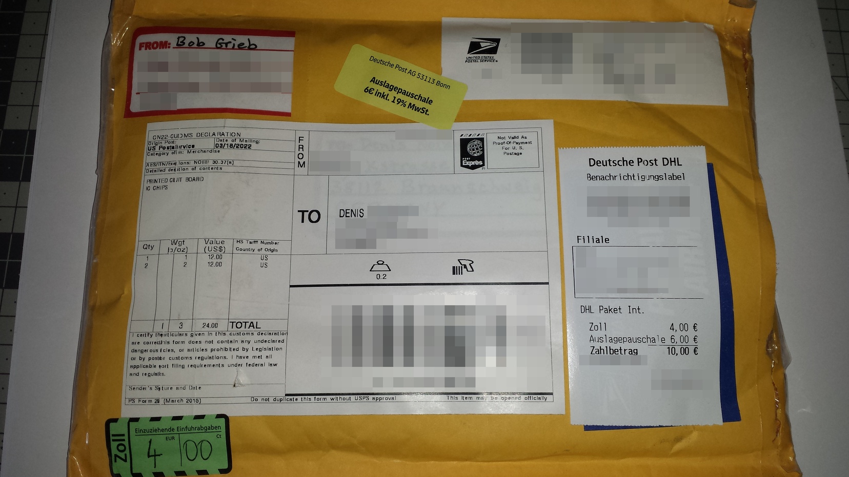
I contacted Bob Grieb of Tauntek and ordered one of his kits back in March 2022. The $35 kit contained the printed circuit board and two pre-programmed PIC microcontrollers. The shipment to Germany cost me about $19 with additional 10 EUR for customs and fees. The total cost for the kit ans shipment was in the order of $64 or approx. 60 EUR. The shipment from USA to Germany took about week and a half.
After receiving Bob’s package, the project got delayed because I’m always kinda busy. I ordered most of the remaining parts via Mouser in December 2022. The ordered parts would cost additional 69 EUR. Many of the components on the bill of materials (BOM) list could have been easily skipped (e. g. resistors and 2x PIC microcontrollers, RS232 level shifter) resulting in 45…48 EUR price range. Nevertheless, I ordered few extra parts just to be sure if anything fails. Extra parts can be always used for different projects or experimenting with other circuits.
Two of needed parts on the BOM weren’t available at the time: the 74HC138 3-to-8 line decoder and LM358AN dual opamp. According to Mouser, the lead times for the decoder were four weeks and for the opamp approx. 1 year (which has been reduced to May 2023 in the meanwhile). So yeah, I had to order both parts on eBay instead. Waiting a year for an opamp wasn’t acceptable. I also ordered an USB to TTL FTDI Serial Adapter on Amazon (2 pieces for 8 EUR) so I could use the Tauntek LogICTester via USB instead of RS232. Everything arrived last week so I had to find few “quiet hours” for the soldering job.
Building the IC Tester
One starts with the printed circuit board and two PIC microcontrollers (U1 as Master and U2 as Slave) as shown in the picture below.

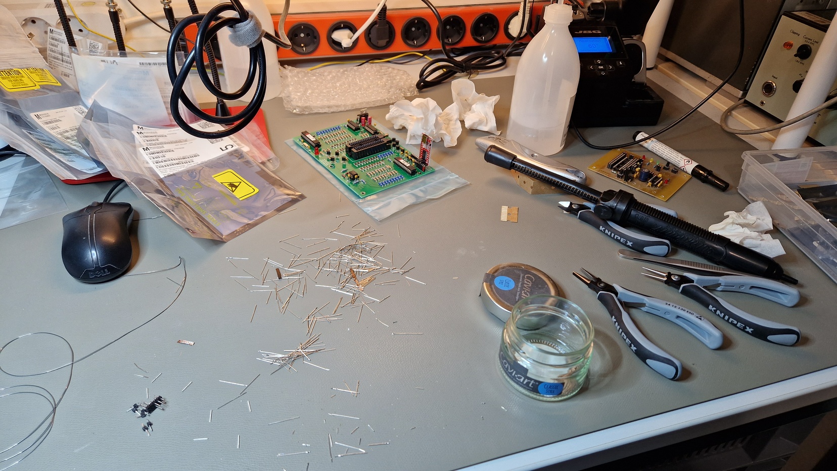
I started populating the resistors and diodes in the first place. After soldering and cutting excess wires, I moved on to capacitors.

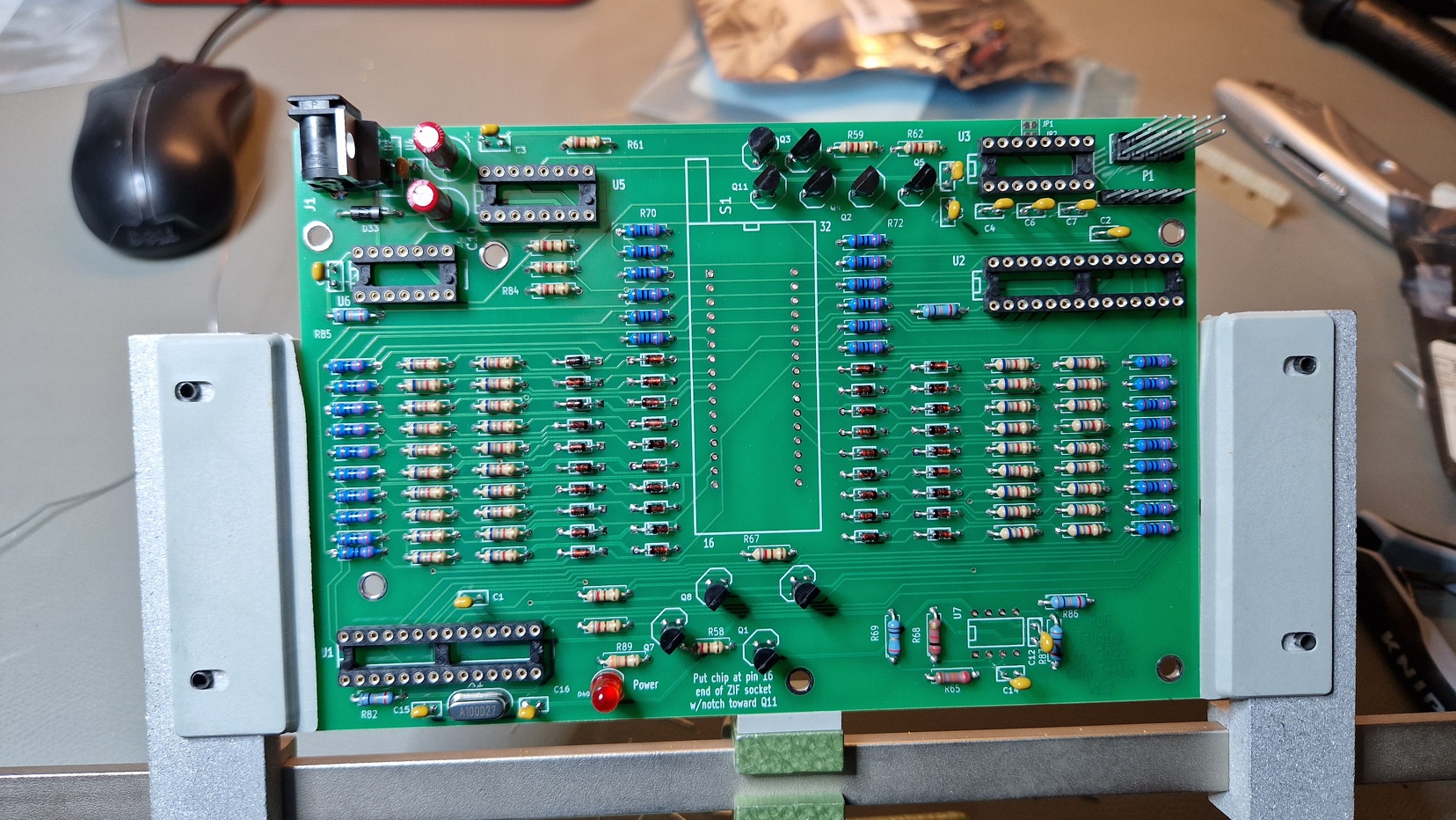
After hours and hours, I finally got it finished. The pins in the top right corner needed to be removed. Also JP1 and JP2 (top right above the IC socket) were shorted by a solder blob in order to use the FTDI to USB adapter instead of the RS232 level shifter. The level shifter 16 pin socket on the top right remains unpopulated. The final assembly can be seen in the picture below.

After assembly I checked for cold joints or shorts. Everything looked fine and I turned it on.

After plugging in the USB cable of the FTDI adapter into the Windows 10 machine, the driver installation started automatically. No additional drivers were needed to be installed. The settings for communication via Serial connection were by default “8-N-1”, which corresponds to 9600 baud, 8 data bits, no parity bit, 1 stop bit and no flow control. The connection needs to be established via a terminal emulator such as PuTTY. After establishing a connecting to the tester, one has to press ENTER to get the welcome screen and voilà, We’re In Like Flynn.
The usage of the IC tester is pretty much straight-forward. Power up the tester, establish a PC connection and put the IC into the socket as shown in the picture above. Enter the IC model inside of the console. If the IC is found inside of the database, type t and press enter to start the IC test. The results are presented in a very comprehensive way. Typing v and pressing enter displays the pin voltages.

That’s it – there isn’t much more to it. Very simple and effective when it comes to debugging the 1970s to 1980s era logic ICs. Few additional hints and comments:
- Unfortunately the IC tester can not be used in order to recognize part numbers of ICs under test. The part numbers have to be looked up manually inside of the terminal emulator (or Bob’s list)
- Bob maintains the firmware and the list of supported ICs. Perhaps by writing him an email and by sending him the missing or unsupported IC, Bob may update his firmware in the future and add support for the missing IC
- The logic tester certainly isn’t free of bugs – some tests may result in a “FAIL” although the IC is still fine according to the datasheet specifications. Please, don’t blindly trust the machine. Take your time and try to sanity-check or interpret the results
- The logic tester can’t check memory chips for faulty memory cells (such as Retro Chip Tester Professional from the 8Bit-Museum.de)
- I’ve added a picture gallery to my Piwigo website if you want to check out some additional pictures
Have a nice Sunday and happy IC testing!