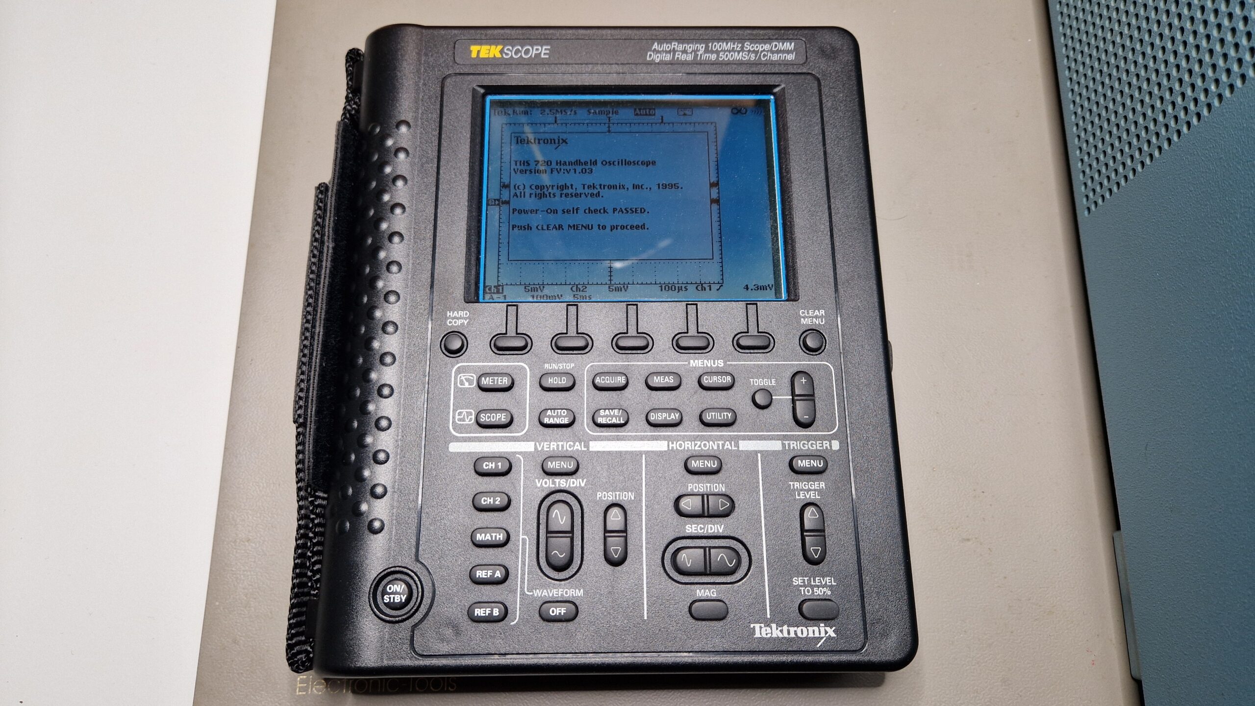
Recharging Ni-Cd batteries for Tektronix THS 720 STD portable oscilloscope
Merry day after Christmas everyone! I hope everyone is having a good time and doing fun projects during holidays and vacation. I’m trying to write a blog post again, so today’s blog entry will be about some of my efforts to recharge a battery! Can’t be that hard, can it?
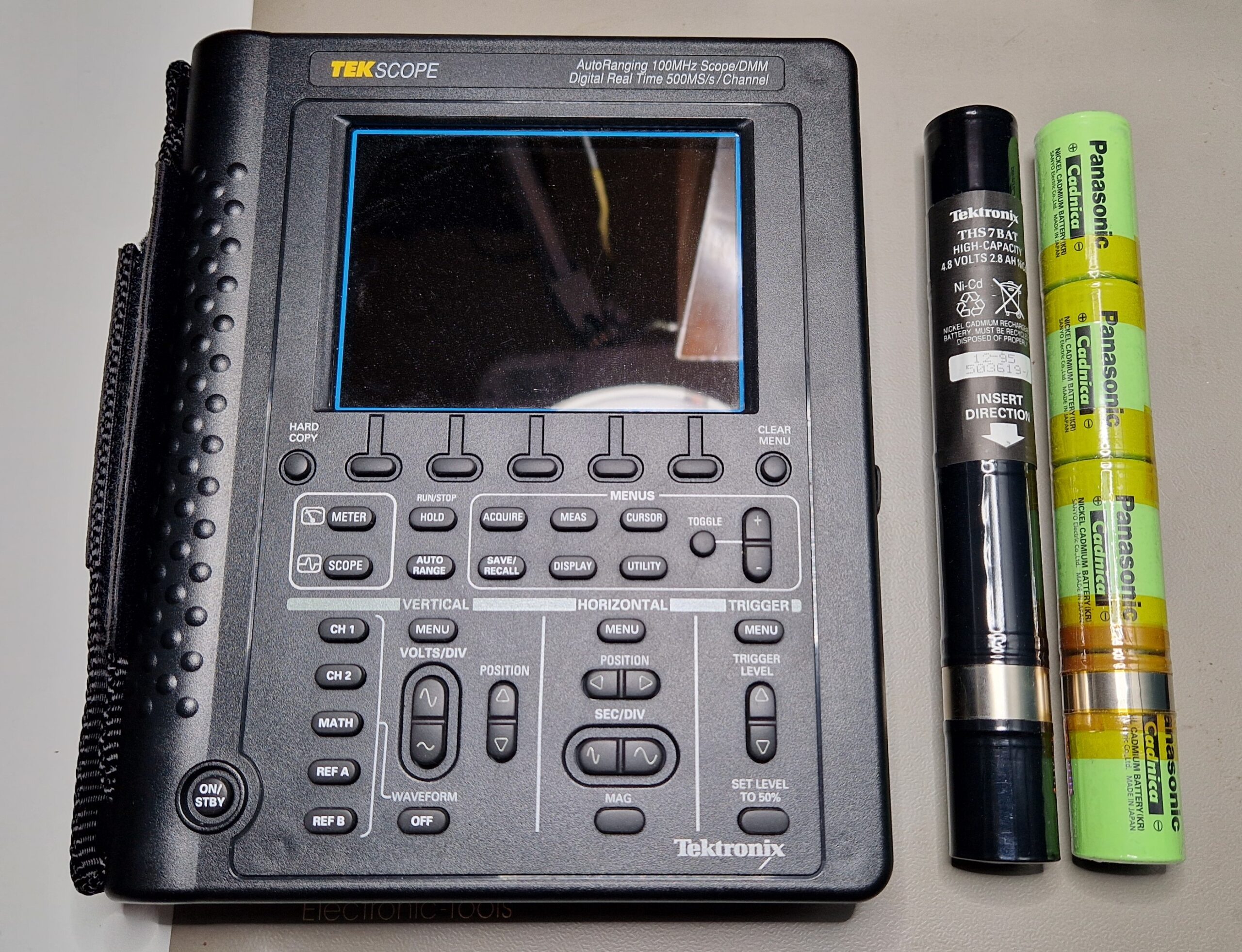

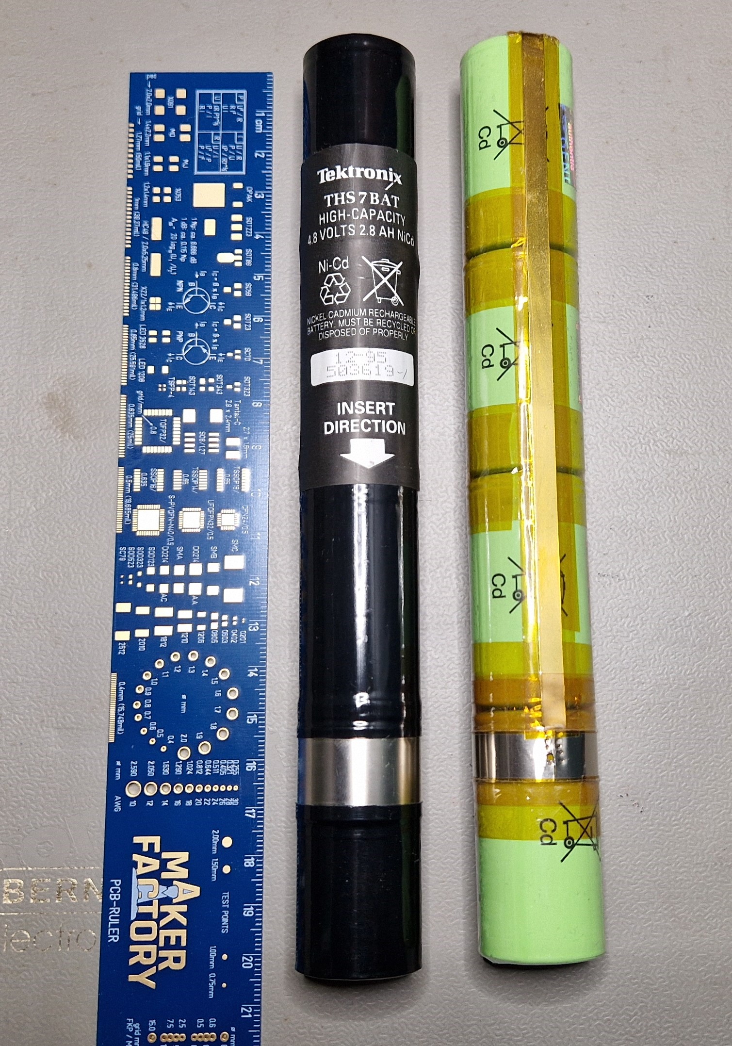


Anyways, the Panasonic Cadnica replacement batteries turned out to work exceptionally well and provided enough power for a certain amount of time (depends on oscilloscope usage, perhaps 1 day with intermittent usage). I didn’t use the oscilloscope very much in the past and the battery was discharged as expected. In order to recharge the battery, I originally used the oscilloscope’s internal charging circuit, which “kinda” did the job. The charging at supplied voltage of 12 V and 1 A took around 24 hours. I noticed a significant heat-up of the battery packs up to ~45 °C, maybe 50 °C so I wasn’t quite sure about the unsupervised safety of this charging procedure. The max. charging temperature according to the datasheet is specified at +45 °C so I really hit the temperature limit. To avoid this in the future, I was looking for a fast Ni-Cd charger where I could quickly recharge the batteries without a significant heat build-up. There is a Tektronix THS7CHG Battery Charger on the 2nd hand market (e. g. eBay), however, it’s too rare and too expensive and not a viable option. An EEVblog user has constructed a similar charger with off-the-shelf components and 3D-printed housing. For a single Ni-Cd cell, the rapid charging time should be in the order of 1 … 2 hours at a nominal Voltage of 1.2 V and maximum currents of up to 4500 mA – compared to the 16-24 hours at standard charging currents (300 mA).


For this purpose, I bought a 2nd hand discontinued universal charger, which are very common in the fields of radio-controlled toys and RC models (drones, cars, boats etc.). It was manufactured by a German company called Robbe (type: Power Peak Infinity 2), which is capable of charging and discharging different types of batteries (NiMH, Lead Acid, Ni-Cd). In order to operate it, one needs a (switch-mode) power supply which provides the necessary voltages and currents for operation of the charger (e. g. 13.8 V and 0.1 … 5 A). The battery charger’s microcontroller monitors and regulates the output voltages and currents, which suits the charging profile of the batteries being recharged. In case of 4 Ni-Cd batteries, we need at least 4x 1.2 V = 4.8 V with a current limitation of 4.5 A (according to the Cadnica datasheet). The charging speed is limited by the battery temperature, the build-up of internal pressure and the so-called charge rate C. Typical charge rates are around 0.1 C while “fast” charge rates are around 0.5 C up to 1 C. Due to limitations of Ni-Cd batteries (memory effect, ~500 recharging cycles), they should be discharged first, then recharged at low rates (e. g. 0.1 C) to increase their longevity. For long-term storage of Ni-Cd batteries, Robbe user manual recommends to discharge them first and store them in a cold and dry place (e. g. in a fridge at 4 °C) in order to mitigate the performance deterioration due to the memory effect.

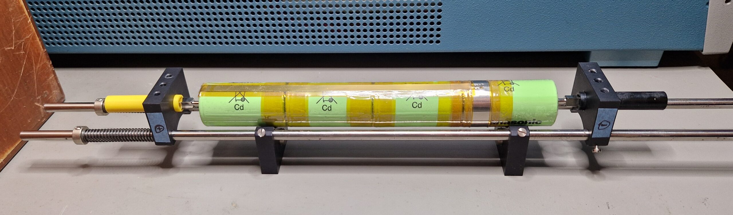
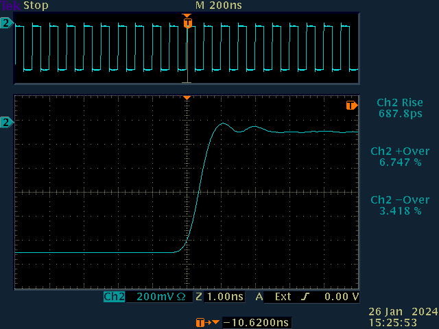
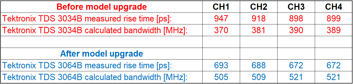
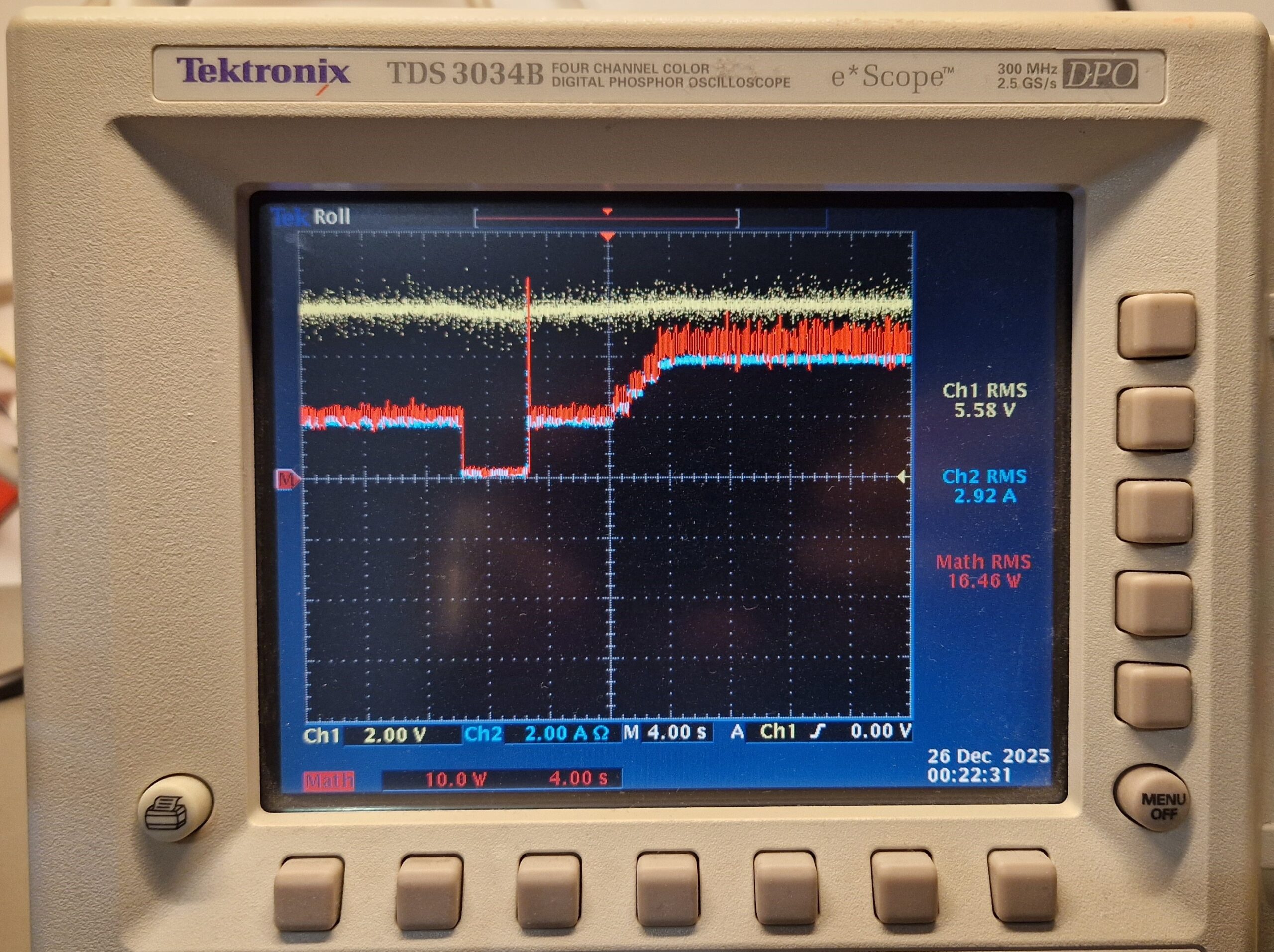
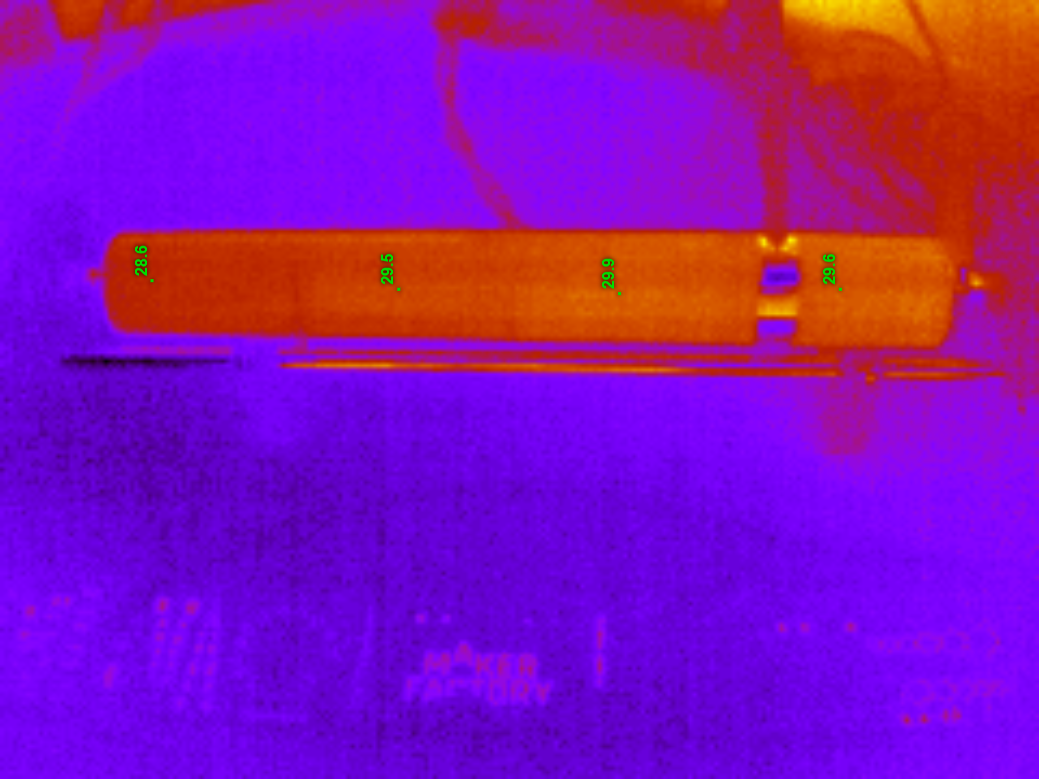
My charging/discharging setup looks as follows: the switch-mode power supply (JAMARA Germany DC Regulated Power Supply, Output: 13.8 V & 0-20 A) is connected to the charger. The charger output is then connected to the battery pack fixture. For my battery fixture, I used some spare optics parts I had at hand. The spring-loaded electrode helps to keep the battery in place and also helps to provide a reliable electrical contact. The recharger was powered on and set up to the “DISCHARGE -> CHARGE” mode, which is recommended by the Robbe manual. The battery under test had a remaining voltage of about 2.4 V and was discharged with a current of about 0.1 to 0.3 A. As soon as the battery was discharged to a certain threshold voltage (e. g. 1 V open circuit voltage), the charging cycle began by a slow ramp-up of the voltages and currents. After few minutes, the rapid charging is reached at approx. 6 V and 4.5 A (about 30 W), which corresponds to a charge rate of 1.5 C. I could observe some kind of a charge duty cycle, where the current flow stopped for a certain amount of time before continuing again – perhaps for thermal management purposes. The charging process took about 60 minutes, the estimated restored battery capacity (= transferred charge) was in the order of 3000 mAh. The temperature of the setup was monitored during the charging process with a thermal camera, however the battery pack didn’t heat up significantly in comparison to the mentioned THS 720 internal battery charger. The voltages were monitored by a digital multimeter HP 34401A and an oscilloscope Tektronix TDS 3064B, the current was monitored by a Tektronix TCP 202 current probe. This allowed me to estimate the power demand during the charging process.


I was surprised how well and how fast this recharging process went. The DIY battery pack proved to be suitable alternative to the original battery pack Tektronix THS7BAT. Unfortunately, the Ni-Cd batteries age and need to be replaced over time. However, an inexpensive alternative with modern-day parts for a reasonable amount of money (~30 … 40 EUR) can be used to replace the original battery pack and extend the lifetime of the oscilloscope usage, at least until the internal electronic parts start to fail (e. g. the opto-couplers of this scope).
Recharging Ni-Cd batteries for Tektronix THS 720 STD portable oscilloscope Read More »