Tektronix TDS 3034B bandwidth upgrade

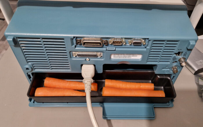
A “new” oscilloscope arrived in the lab just recently thanks to my friend Matt, who relayed the offer to me. It’s a wonderful instrument from the early 2000’s era: a Tektronix TDS 3034B Four Channel Color Digital Phosphor Oscilloscope. The oscilloscope’s analog bandwidth is specified at 300 MHz with a sample rate of 2.5 GS/s per each channel. It has a ton of options (e. g. FFT, 3LIM, 3TRG) and a communication module with VGA monitor output and GPIB/Ethernet/RS-232 for communication and control. There is also a battery compartment, however, the battery was not included. The “Waveform Intensity” knob simulates the intensity control of an analog oscilloscope with a cathode ray tube – therefore a “Digital Phosphor Oscilloscope” or DPO. The size of the oscilloscope is very convenient and perfect for a desk use – doesn’t take much space and it’s fast and responsive compared to my older Tektronix TDS 754D oscilloscope.

I was able to set up the communication to my PC via GPIB (IEEE 488). Since I already had the Tektronix WaveStar Software for Oscilloscopes installed on my Windows 10 PC, I was able to quickly transfer screenshots/hardcopies, measurement data and sample data from the instrument to my PC. No diskettes or USB drives were needed. It is possible to control the oscilloscope remotely which is absolutely fantastic for measurement documentation and measurement automation purposes! It’s a great addition to the lab and it will serve to me as my daily workhorse among other oscilloscopes, of course.

Bandwidth Upgrade
It seems to be very common (even nowadays in 2024) that the oscilloscope manufacturers design a generic oscilloscope parts which can be used for different models. The oscilloscopes are then assembled with similar to identical hardware components (presumably because it’s cheaper manufacturing-wise) but the measurement capabilities are determined either by hardware (jumper settings) or by software (locked/unlocked options). For example, Rigol DHO 800/900 Series Oscilloscopes can be upgraded from 70 MHz to 100+ MHz via software. Thanks to Matt, he gave me a hint that the guys at EEVblog have figured out how to perform an upgrade of the Tektronix TDS Series oscilloscopes to different models. So already having an excellent 300 MHz & 2.5 GS/s oscilloscope at my fingertips, I was curious if I could upgrade it to the 3064B model which has 600 MHz analog bandwidth and 5 GS/s sample rate. I tried out the EEVblog’s upgrade procedure and it seemed to work without bricking the oscilloscope. I’ll just quickly summarize the procedure here.
- Boot up the device and set up the communication via GPIB (e. g. GPIB address and talker/listener mode). Connect the device to your GPIB controller
- I used the National Instruments GPIB-USB-HS controller device along with current NI’s GPIB drivers (driver version doesn’t matter much, you could also use the VISA drivers from Keysight, Tektronix or Keithley). The TDS 3034B Firmware Version was
v3.39 - The communication between the PC and the oscilloscope was established with NI Measurement & Automation eXplorer’s (NI MAX) own GPIB Instrument Communication. I guess you could use any GPIB communication software, e. g.
pyvisafor Python - Check whether the oscilloscope responds to the
*IDN?query. If yes, proceed, if not – try to find the problem and fix it (obviously) - Send the following commands to the oscilloscope
PASSWORD PITBULL
MCONFIG TDS3064B
Just send (write) the commands in the order as shown above! Do not use a “GPIB query” since there will be no response action from the oscilloscope. Upper/lower case letters don’t matter. - Now power-cycle the oscilloscope (turn it off, wait few seconds and turn it on again). It should boot up with a new screen and new model. If it doesn’t show the new model, something went wrong with command transmission via GPIB. As far as I could tell, some models accept only different
MCONFIG-commands, such as “MCONFIG TDS3054” without the letter “B” at the end. Anyways, after sending the commands via GPIB and power-cycling the oscilloscope, it should show up with the new model - Changing the TDS model will result in an uncompensated waveform. I observed a DC offset and noise on my CH1 through CH4 waveforms post-update. The solution to this problem is quite easy: wait some time (at least 10-15 minutes) for a warm-up and perform the Signal Path Compensation (SPC), which can be found in the
Utility → System Config → Cal
menu. This will perform an internal calibration where the noise and offset errors are compensated. The oscilloscope should be ready for performing measurements afterwards
That’s how it worked out for me. It took me just few minutes to convert a Tektronix TDS 3034B into a TDS 3064B. I’d recommend to check out the linked EEVblog thread for further information on the TDS 1000/2000/3000 Series upgrades. Of course I can’t be held responsible if you try it out and damage your instrument (e. g. calibration data or warranty is lost or the device is bricked) since I’m sharing this information and tried it out on my own oscilloscope. This is solely done at one’s own risk! Please be careful when trying out this procedure and please read the EEVblog thread prior to changing the instrument. Always make backups of your oscilloscope firmware prior to changes. Also hacking the device in order to use unlicensed software options is… well… “illegal”… I guess… Keysight’s Agents will hunt your PC down! 😉

Checking the Oscilloscope Analog Channel Bandwidth
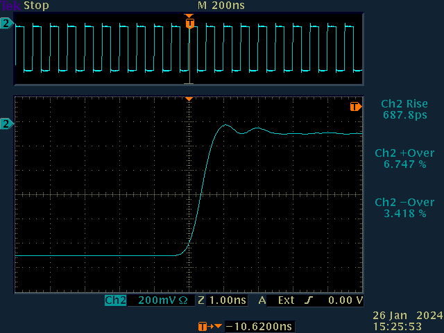
I did some initial bandwidth testing with my Leo Bodnar Fast Risetime Pulse Generator. The pulser generates repetitive 10 MHz square waves (~1 Vpp) with a rise time of around (30 ± 2) ps. It can be used to easily test the oscilloscope’s analog channel input bandwidth. The analog bandwidth of an oscilloscope can be calculated as follows:
\( \mathrm{BW [GHz]} \approx \cfrac{0.35}{t_r ~\mathrm{[ns]} } \)So a measured 10%-90% rise time of \(t_r = 1.000 ~\mathrm{ns}\) results in an analog bandwidth of \(0.35/(1.000 \cdot 10^{-9} ~\mathrm{s}) \approx 0.350 \cdot 10^9 ~\mathrm{Hz}\) or 0.35 GHz which is basically 350 MHz. So prior to the bandwidth upgrade we were expecting an oscilloscope bandwidth of ~300 MHz at a 2.5 GS/s sample rate, post-upgrade it should be around ~600 MHz and a 5 GS/s sample rate. I’ve measured the rise time of all four channels in order to see if there are any significant differences between them. The oscilloscope settings were as follows: Coupling: DC, Termination: 50 Ω, Trigger: External, Acquisition Mode: 64× average per acquisition at 10k points and 5.00 GS/s. The trigger was delayed by approx. -10 ns.
The measurement results are summarized in the table below.

As we can see, the full bandwidth of 600 MHz for a Tektronix TDS 3064B has not been achieved. However, there is a measurable improvement. Channels 3 and 4 seem to have a slightly higher bandwidth than channels 1 and 2. The rise time measurements deviate on each acquisition so I would estimate an uncertainty in the rise time measurements of approx. ±10 ps. I also wonder if the overshoot/undershoot calculations are correct. I’ll have to look into this manually, since the data samples can be exported in a CSV file.
Conclusion
Nevertheless, the bandwidth upgrade was successful! 500 MHz analog bandwidth at 5 GS/s is more than enough for my needs before stepping into the GHz time domain regime. And no need for a battery if there is a food compartment in your oscilloscope! Tested successfully with carrots! 😉

Tektronix TDS 3034B bandwidth upgrade Read More »


